Developing and Testing Fixed-Point Systems
The Fixed-Point Designer™ software provides tools that aid in the development and testing of fixed-point dynamic systems. You directly design dynamic system models in the Simulink® software that are ready for implementation on fixed-point hardware. The development cycle is illustrated below.
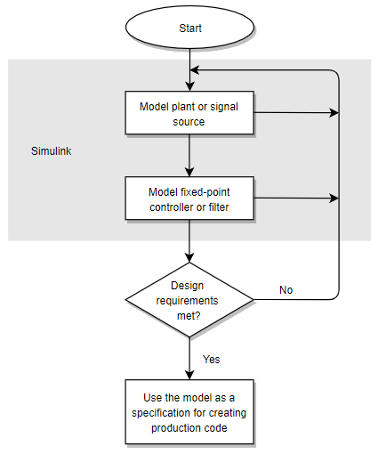
Using the MATLAB®, Simulink, and Fixed-Point Designer software, you follow these steps of the development cycle:
Model the system (plant or signal source) within the Simulink software using double-precision numbers. Typically, the model will contain nonlinear elements.
Design and simulate a fixed-point dynamic system (for example, a control system or digital filter) with fixed-point Simulink blocks that meets the design, performance, and other constraints.
Analyze the results and go back to step 1 if needed.
When you have met the design requirements, you can use the model as a specification for creating production code using the Simulink Coder™ product or generating HDL code using the HDL Coder™ product.
The above steps interact strongly. In steps 1 and 2, there is a significant amount of freedom to select different solutions. Generally, you fine-tune the model based on feedback from the results of the current implementation (step 3). There is no specific modeling approach. For example, you may obtain models from first principles such as equations of motion, or from a frequency response such as a sine sweep. There are many controllers that meet the same frequency-domain or time-domain specifications. Additionally, for each controller there are an infinite number of realizations.
The Fixed-Point Designer software helps expedite the design cycle by allowing you to simulate the effects of various fixed-point controller and digital filter structures.