Generate HDL Code from a MATLAB Function Block
This example shows how to construct and configure a simple model and then generate VHDL code from the model.
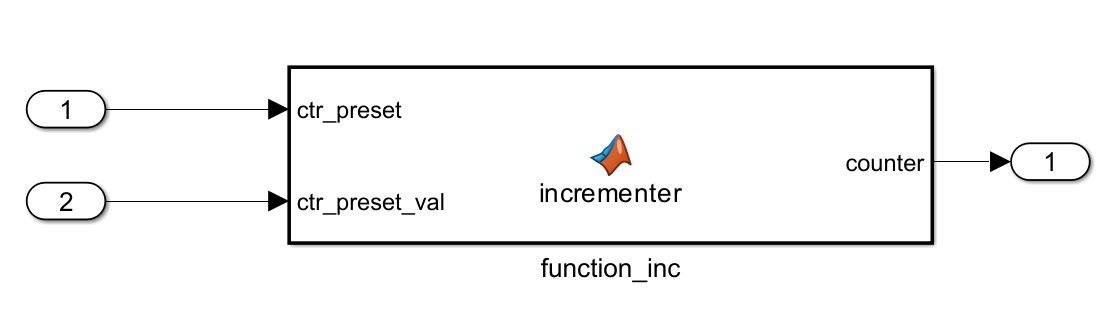
The MLHDLIncrementer model in this example includes a MATLAB Function block that implements a simple fixed-point counter function, incrementer. The incrementer function is invoked once during each sample period. The function maintains a persistent variable count that the function either increments or reinitializes to a preset value, ctr_preset_val, depending on the value passed to the ctr_preset input of the MATLAB Function block. The function returns the counter value, counter, at the output of the MATLAB Function block.
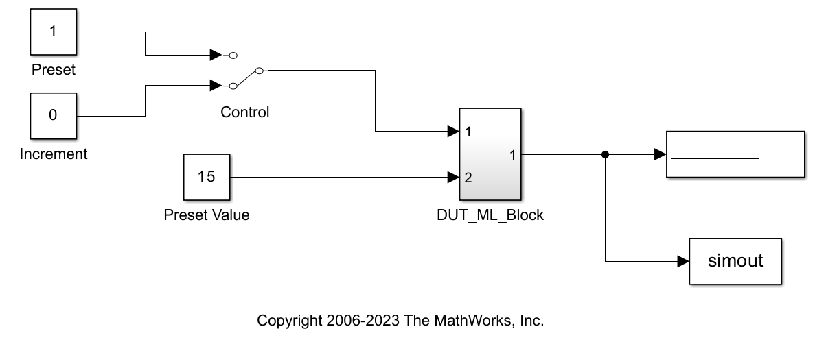
The MATLAB Function block resides in a subsystem named DUT_ML_Block. The subsystem functions as a device under test (DUT) from which you generate HDL code.
The root-level model drives the subsystem and includes Display and To Workspace blocks. The Display and To Workspace blocks do not generate HDL code.
Create and Configure the Model
Create a model and run the hdlsetup command to set some model configuration parameters to values recommended for HDL code generation. The hdlsetup command uses the set_param function to set up models for HDL code generation. To customize the hdlsetup command, see Customize hdlsetup Function Based on Target Application.
Before you begin building the example model, set up a working folder for your model and generated code. This folder stores the model you create, and also contains subfolders of the generated code. The location of the folder does not matter, except that it should not be within the MATLAB tree.
1. Create a new model.
2. Save the model as MLHDLIncrementer.
3. In the MATLAB Command Window, enter:
hdlsetup('MLHDLIncrementer');
4. In Simulink, open the Configuration Parameters dialog box.
5. In the Solver pane, set these configuration parameters:
Fixed step size (fundamental sample time):
1Stop time:
5
6. Click OK to save your changes and close the Configuration Parameters dialog box.
7. Save your model.
Add a MATLAB Function Block to the Model
1. Open the Library Browser. Then, select the Simulink > User-Defined Functions library.
2. Select the MATLAB Function block and add it to the model.
3. Change the block label to function_inc.

4. Close the Library Browser.
5. Save the model.
Set Fixed-Point Settings for the MATLAB Function Block
Configure the MATLAB Function block with the recommended fimath specifications. To configure the block:
1. Double-click the MATLAB Function block. The MATLAB Function block editor opens.
2. In the Modeling tab, in the Design section, click the Property Inspector. The Property Inspector displays the default fimath specification and other properties for the MATLAB Function block.
3. Expand the Fixed-point properties section and select Specify Other. Selecting this option enables the MATLAB FUNCTION FIMATH text entry field.
4. The hdlfimath function is a utility that defines a fimath specification optimized for HDL code generation. Replace the default specification in the MATLAB FUNCTION FIMATH field with:
hdlfimath;
This function sets these fimath specification properties to these settings:
ProductModeproperty:'FullPrecision'SumModeproperty:'FullPrecision'
5. Set the Treat these inherited signal types as fi objects property to Fixed-point.
6. Save the model.
Program the MATLAB Function Block
Next, add the code to the MATLAB Function block to define the incrementer function, and then use diagnostics to check for errors.
1. In the MATLAB Function block editor, delete the default code.
2. Add this code into the editor:
function counter = incrementer(ctr_preset, ctr_preset_val)
% The function incrementer implements a preset counter that counts
% how many times this block is called.
%
% This example function shows how to model memory with persistent variables,
% using fimath settings suitable for HDL. It also demonstrates MATLAB
% operators and other language features that HDL Coder supports
% for code generation from Embedded MATLAB Function block.
%
% On the first call, the result 'counter' is initialized to zero.
% The result 'counter' saturates if called more than 2^14-1 times.
% If the input ctr_preset receives a nonzero value, the counter is
% set to a preset value passed in to the ctr_preset_val input.


persistent current_count;
if isempty(current_count)
    % zero the counter on first call only
    current_count = uint32(0);
end


counter = getfi(current_count);

if ctr_preset
    % set counter to preset value if input preset signal is nonzero
    counter = ctr_preset_val;
else
    % otherwise count up
    inc = counter + getfi(1);
    counter = getfi(inc);
end

% store counter value for next iteration
current_count = uint32(counter);

end

function hdl_fi = getfi(val)

nt = numerictype(0,14,0);
fm = hdlfimath;
hdl_fi = fi(val, nt, fm);

end
3. Save the model. Doing so updates the model window and the MATLAB Function block.
Changing the function header of the MATLAB Function block makes these changes to the block icon:
The function name of the block changes to
incrementer.The arguments
ctr_presetandctr_preset_valappear as input ports to the block.The return value
counterappears as an output port from the block.
4. Resize the block to make the port labels more readable.
5. Save the model again.
Construct and Connect the Subsystem
You construct a subsystem containing the MATLAB Function block to serve as a device under test (DUT) from which you generate HDL code. You then set the port data types and connect the subsystem ports to the model.
To construct the subsystem:
Click the
incrementerblock.On the Modeling tab of the Simulink Toolstrip, select Create Subsystem. A subsystem, labeled
Subsystem, is created in the model window.Change the label of the Subsystem block to
DUT_ML_Block.
To set the port data types for the MATLAB Function block:
Double-click the subsystem to view its contents. The subsystem contains the
incrementerMATLAB Function block and Inport and Outport blocks connected to its ports.Double-click the
incrementerblock to open the MATLAB Function block editor.In the Modeling tab, in the Design section, click Model Explorer.
Click
function_incand selectctr_presetin the middle pane. In the right pane, click the Show data type assistant button to display the Data Type Assistant section. Set Mode to
 Built inand set the data type toboolean. Click Apply.In the middle pane, click
counter. Open the Data Type Assistant. Verify that Mode is set toInherit: Same as Simulink.Return to the top-level model and save it.
To connect the subsystem ports to the model:
Open the Library Browser.
From the Sources library, add a Constant block to the model. Set the value of the Constant block to 1, and the Output data type to
boolean. Change the block label toPreset.Make a copy of the
PresetConstant block. Set its value to 0, and change its block label toIncrement.From the Signal Routing library, add a Manual Switch block to the model. Change its label to
Control. Connect its output to the input port named 1 of theDUT_ML_Blocksubsystem.Connect the
PresetConstant block to the top input port of theControlswitch block. Connect theIncrementConstant block to the bottom input port of theControlswitch block.Add a third Constant block to the model. Set the value of the Constant to 15, and the Output data type to
Inherit via back propagation. Change the block label toPreset Value.Connect the
Preset ValueConstant block to the input port named 2 of theDUT_ML_Blocksubsystem.From the Sinks library, add a Display block to the model. Connect it to the output port named 1 of the
DUT_ML_Blocksubsystem.From the Sinks library, add a To Workspace block to the model. Branch the output signal from the
DUT_ML_Blocksubsystem to the To Workspace block.Save the model.
Use the built-in diagnostics of the MATLAB Function block to test for syntax errors:
Open the
DUT_ML_Blocksubsystem.Double-click the MATLAB Function block.
In the Function tab, click Update Model to compile and build the MATLAB Function block code.
The build process displays some progress messages.
The build process builds an S-function for use in simulation. During the build process, the software generates C code for this S-function. The code generation messages you see during the build process refer to generation of C code, not HDL code generation.
When the build concludes without encountering an error, a message window indicates that parsing was successful. If errors are found, the Diagnostics Manager lists them. For more information on debugging MATLAB Function block build errors, see MATLAB Function.
Compile the Model and Display Port Data Types
When you compile the model, Simulink verifies the model structure and settings, and updates the model display.
In the Debug tab of the Simulink Toolstrip, click Information Overlays > Ports. In the Ports section, select Base data types.
Press Ctrl+D to compile and update the model. This action rebuilds the code. After the model compiles, the block diagram updates to show the port data types.
Save the model.
Simulate the Model
Start simulation by clicking the Run button on the Simulation tab. If required, the code rebuilds before the simulation starts.
After the simulation completes, the Display block shows the final output value returned by the incrementer function block. For example, given a Start time of 0, a Stop time of 5, and a zero value at the input port 1, the simulation returns a value of 6.
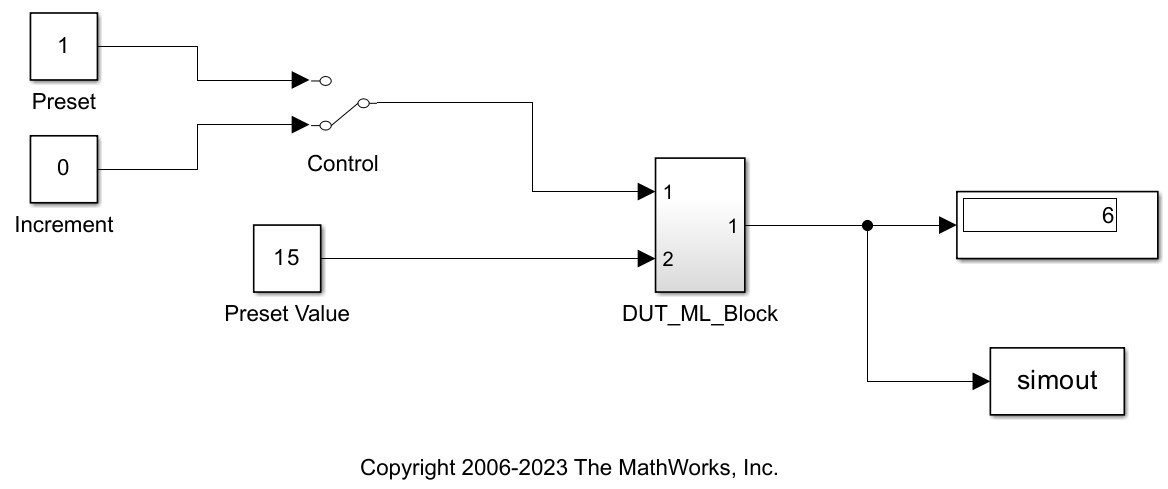
You can experiment with the results of toggling the Control switch, changing the Preset Value constant, and changing the total simulation time. You can also examine the workspace variable simout, which is bound to the To Workspace block.
Generate HDL Code
To generate HDL code for the model, you first select the DUT_ML_Block subsystem for HDL code generation, set basic code generation configurations, and then generate VHDL code for the subsystem.
Select the DUT_ML_Block subsystem and configure it for HDL code generation:
1. Open the Configuration Parameters dialog box and click the HDL Code Generation pane.
2. Ensure that these parameters are set as follows:
Generate HDL for: MLHDLIncrementer/DUT_ML_Block
Language: VHDL
Folder: hdlsrc
The Folder field specifies the code generation target folder. This folder is a subfolder of your working folder. Before generating code, make sure you are in the current working folder.
To generate code:
1. In Simulink Toolstrip, from the Apps gallery, click HDL Coder. In the HDL Code tab, click Generate HDL Code.
HDL Coder™ compiles the model before generating code. Depending on model display options, such as the port data types, the appearance of the model might change after code generation.
2. As code generation proceeds, the Diagnostic Viewer displays progress messages. The process should complete with a message like the following:
### HDL Code Generation Complete.
In the Diagnostic Viewer, the names of generated VHDL files in the progress messages are hyperlinked. After code generation completes, you can click these hyperlinks to view the files in the MATLAB editor.
3. The code generation process created the hdlsrc folder as a subfolder of your working folder. To view generated code and script files, double-click the hdlsrc folder in Current Folder browser.
4. Observe that two VHDL files were generated. The structure of HDL code generated for MATLAB Function blocks is similar to the structure of code generated for Stateflow® charts and Digital Filter blocks. The VHDL files that were generated in the hdlsrc folder are:
function_inc.vhd: VHDL code. This file contains entity and architecture code that implements the computations generated for the MATLAB Function block.DUT_ML_Block.vhd: VHDL code. This file contains an entity definition and RTL architecture that provides a black box interface to the code generated infunction_inc.vhd.
The structure of these code files is analogous to the structure of the model, in which the DUT_ML_Block subsystem provides an interface between the root model and the incrementer function in the MATLAB Function block.
The other files generated in the hdlsrc folder are:
DUT_ML_Block_compile.do: Mentor Graphics® ModelSim® compilation script (vcomcommand) that compiles the VHDL code in the two.vhdfiles.DUT_ML_Block_map.txt: Mapping file. This report file maps generated entities, or modules, to the subsystems that generated them. See Trace Code Using the Mapping File.
To view the generated VHDL code in the MATLAB editor, double-click the DUT_ML_Block.vhd or function_inc.vhd files in the Current Folder browser.
See Also
Check for MATLAB Function block settings
Related Topics
You can also select a web site from the following list:
Americas
- América Latina (Español)
- Canada (English)
- United States (English)
Europe
- Belgium (English)
- Denmark (English)
- Deutschland (Deutsch)
- España (Español)
- Finland (English)
- France (Français)
- Ireland (English)
- Italia (Italiano)
- Luxembourg (English)
- Netherlands (English)
- Norway (English)
- Österreich (Deutsch)
- Portugal (English)
- Sweden (English)
- Switzerland
- United Kingdom (English)