Gas-Charged Accumulator (TL)
Gas-charged accumulator in a thermal liquid network
Libraries:
Simscape /
Fluids /
Thermal Liquid /
Tanks & Accumulators
Description
The Gas-Charged Accumulator (TL) block represents a pressurized thermal liquid container with a compressed gas charge. The accumulator consists of thermal liquid and gas chambers separated by a hermetic and insulated diaphragm.
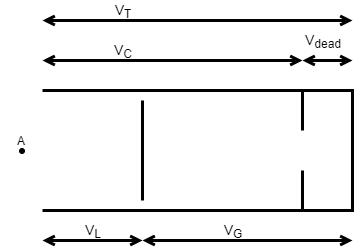
Accumulator Schematic

If the inlet pressure is greater than the gas charge pressure, the liquid chamber volume increases, compressing the gas chamber. If the inlet pressure is lower than the gas charge pressure, the liquid chamber volume decreases, decompressing the gas chamber.
Hard stops limit the diaphragm motion when the liquid chamber is at capacity and when the liquid chamber is empty. If the specified spring stiffness is too low, the liquid volume can momentarily fall below zero or rise above capacity. Use the Hard stop stiffness coefficient parameter to correct this.
Mass Balance
The mass conservation equation in the liquid chamber is
where:
ρL is the thermal liquid density.
βL is the isothermal bulk modulus.
αL is the isobaric thermal expansion coefficient.
pL is the thermal liquid pressure.
TL is the thermal liquid temperature.
is the thermal liquid mass flow rate into the accumulator through port A.
The block computes the time variation of the liquid chamber volume using the conditional equation
where:
Ks is the Hard-stop stiffness coefficient parameter.
Kd is the Hard-stop damping coefficient parameter.
is the mass flow rate into the liquid chamber when the accumulator diaphragm contacts the top hard stop:
is the mass flow rate from the liquid chamber when the accumulator diaphragm contacts the bottom hard stop:
Momentum Balance
The momentum conservation equation in the accumulator volume is
where pHS is the hard-stop contact pressure:
Energy Balance
The energy conservation equation in the liquid chamber volume is
where:
uL is the thermal liquid specific internal energy.
ΦA is the energy flow rate into the liquid chamber through the accumulator inlet.
ΦH is the thermal energy flow rate into the liquid chamber through the accumulator wall.
Chamber Volumes
The liquid chamber volume is the difference between the total accumulator volume and the gas chamber volume:
where:
VL is the liquid chamber volume.
VT is the total accumulator volume.
VG is the gas chamber volume.
Chamber Volumes

The liquid chamber capacity is the difference between the total accumulator volume and the dead volume of gas in the accumulator at full capacity:
where:
VC is the liquid chamber capacity.
VDead is the dead volume of gas at full capacity.
The gas chamber pressure and volume follow from the precharge states as described by the polytropic equation
where:
pG is the gas chamber pressure at a given time step.
VG is the gas chamber volume at a given time step.
ppr is the precharge gas chamber pressure when the liquid chamber is empty.
VT is the total liquid chamber volume.
k is the polytropic index.
Initial Targets
To set the priority and initial target values for the block variables prior to simulation, use the Initial Targets section in the block dialog box or Property Inspector. For more information, see Set Priority and Initial Target for Block Variables.
Nominal values provide a way to specify the expected magnitude of a variable in a model. Using system scaling based on nominal values increases the simulation robustness. Nominal values can come from different sources, one of which is the Nominal Values section in the block dialog box or Property Inspector. For more information, see Modify Nominal Values for a Block Variable.
Assumptions and Limitations
The block treats the gas chamber compression as a polytropic process.
The block ignores diaphragm loading.
The block ignores the effects of fluid inertia.
Examples
Ports
Conserving
Parameters
Extended Capabilities
Version History
Introduced in R2016a

