Multiposition Valve Actuator
Multiposition actuator in any fluid domain
Libraries:
Simscape /
Fluids /
Valve Actuators
Simscape /
Fluids /
Isothermal Liquid /
Valves & Orifices /
Valve Actuators & Forces /
Valve Actuators
Description
The Multiposition Valve Actuator block models a multiposition actuator in any fluid domain. You can use it in combination with any valve block that takes a physical signal as input. The input signal and the switching time affect the actuator position.
Two-Position Actuator Movement
Actuation begins when the value of the signal at port A exceeds 50% of the value of the Nominal signal value parameter. After a time period that equals one third of the value of the Switching-on time parameter, the actuator begins to move toward the limit specified by the Push-pin stroke parameter.
When the value of the signal at port A falls below 50% of the value of the Nominal signal value parameter, the actuator reverses its direction after a time period that equals one third of the value of the Switching-off time parameter. The motion can be interrupted mid-stroke.
In the image above, ton is the value of the Switching-on time parameter. The actuator motion during ton contains an initial rest, a quadratic motion, and a linear motion, represented by tde, tae, and tve, respectively. tde, tae, and tve are all equal length.
The actuator switches direction when the control signal is off. toff is the value of the Switching-off time parameter, during which the actuator repeats the same stages as the switching-on motion. tdr is a stage of rest, tar is a stage of quadratic motion, and tvr is a stage of linear motion. At the end of toff, the actuator position is at the value of the Initial position parameter. tdr, tar, and tvr are all equal length.
When Actuator positions is 2, the
Actuator travel direction parameter sets the direction of
the push-pin motion.
The actuator motion can be interrupted at any time. If the push-pin motion is disrupted mid-stroke, the switch-on and switch-off times are adjusted proportionally to the push-pin position, relative to the push-pin stroke.
Three-Position Actuator Movement
When Actuator positions is set to
3, the signal at port A moves
the actuator in a positive direction and the signal received at port
B moves the actuator in a negative direction. Only one
signal, from one port, is processed at a time. To switch control between ports
A and B, or between positive and
negative displacement control, the actuator must first move to a neutral position.
If the push-pin motion is disrupted mid-stroke, the switch-on and switch-off times
are adjusted proportionally to the push-pin position, relative to the push-pin
stroke. The actuator motion can be interrupted at any time.
When controlled by the signal at port A, the three-position
actuator has the same displacement profile as the two-position actuator when
Actuator travel direction is set to
Positive. When controlled by the signal at port
B, it has the same profile as the two-position actuator
when Actuator travel direction is set to
Negative.
Examples
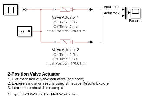
2-Position Valve Actuator
Demonstrates the Multiposition Valve Actuator block with two positions. The same signal controls two valve actuators, but the actuators use different values of the Switching-on time, Switching-off time, and Initial position parameters.
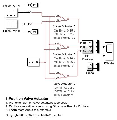
3-Position Valve Actuator
The behavior of three different Multiposition Valve Actuator blocks. In each block Actuator positions is 3. All three actuators are driven by the same pulse signals. The values of the Push-pin stroke, Switching-on time and Switching-off time parameters of the three actuators are different, which illustrates the parameter impact.
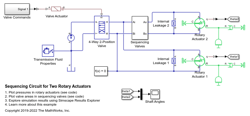
Sequencing Circuit for Two Rotary Actuators
A sequencing circuit that is based on four check valves installed in the pressure and return lines of the second rotary actuator. The cracking pressure of the meter-in check valves is set high enough to prevent flow into rotary actuator 2 while rotary actuator 1 is rotating, but lower than the pressure that develops once rotary actuator 1 reaches its hard stop. As a result, rotary actuator 2 starts moving only after rotary actuator 1 completes its stroke.
Ports
Input
Output
Parameters
Extended Capabilities
Version History
Introduced in R2020a