Orifice (2P)
Constant- or variable-area orifice in a two-phase fluid network
Libraries:
Simscape /
Fluids /
Two-Phase Fluid /
Valves & Orifices
Description
The Orifice (2P) block models pressure loss due to a constant or variable area orifice in a two-phase fluid network. The Modeling option parameter controls the parameterization options for a valve designed for modeling either vapor or liquid, but does not impact the fluid properties. The block calculates fluid properties inside the valve from inlet conditions. There is no heat exchange between the fluid and the environment, and therefore phase change inside the orifice only occurs due to a pressure drop or a propagated phase change from another part of the model.
The orifice can be constant or variable. When Orifice type is
Variable, the physical signal at port
S sets the position of the control member, which opens and
closes the orifice.
Liquid Orifice
When Modeling option is Liquid operating
condition, the block parameterizations depend on the value of the
Orifice type parameter. The block calculates the pressure
loss and pressure recovery in the same way for all liquid parameterization
options.
The block accounts for pressure loss by using the ratio of the pressure loss across the whole orifice to the pressure drop immediately across the orifice plate. This ratio, PRloss, is
where:
Cd is the value of the Discharge coefficient parameter.
Aorifice is the instantaneous orifice open area.
Aport is the value of the Cross-sectional area at ports A and B parameter.
The pressure recovery is the positive pressure change in the valve due to an increase in area after the orifice hole. If you do not want to capture this increase in pressure, clear the Pressure recovery check box. In this case, PRloss is 1, which reduces the model complexity. Clear this setting if the orifice hole is quite small relative to the port area or if the next downstream component is close to the block and any jet does not have room to dissipate.
The critical pressure difference, Δpcrit, is the pressure differential where the flow transitions between laminar and turbulent flow,
where:
pA and pB are the pressure at port A and B, respectively.
Blam is the value of the Laminar flow pressure ratio parameter.
When you set Orifice type to Constant and
Orifice Parameterization to Nominal mass
flow rate, the mass flow rate through the orifice is
where:
is the value of the Nominal mass flow rate parameter.
Δpnom is the value of the Nominal pressure drop rate parameter.
vnom is the nominal inlet specific volume. The block determines this value from the tabulated fluid properties data based on the value of the Nominal inlet condition specification parameter.
vin is the inlet specific volume.
When you set Orifice type to Constant and
Orifice Parameterization to Orifice
area, the block calculates the mass flow rate as
where Δp is the pressure drop over the orifice, pA ̶ pB.
When you set Orifice type to Variable and
Orifice Parameterization to Nominal mass
flow rate vs. control member position, the mass flow rate
through the variable-area orifice is
where λ is the orifice opening fraction, which is a fraction of the total orifice open area.
The block determines the orifice opening for all variable orifice parameterizations as
where:
ε is
1when Opening orientation isPositive control member displacement opens orificeand-1when Opening orientation isNegative control member displacement opens orifice.fleak is the value of the Leakage flow fraction parameter.
S is th value of the signal at port S.
Smin is the value of the Control member position at closed orifice parameter.
ΔS is the value of the Control member travel between closed and open orifice parameter.
When you set Orifice type to
Variable and Orifice
Parameterization to Linear - Area vs. control member
position, the orifice area is
where Amax is the value of the Maximum orifice area parameter.
The mass flow rate is
When the orifice is in a near-open or near-closed position, you can maintain numerical robustness in your simulation by adjusting the Smoothing factor parameter. If the Smoothing factor parameter is nonzero, the block smoothly saturates the opening area between Aleak and Amax, where Aleak = fleakAmax. For more information, see Numerical Smoothing.
When you set Orifice type to Variable and
Orifice Parameterization to Tabulated data
- Area vs. control member position, the block interpolates the
orifice area, Aorifice, from the
Orifice area vector and Control member
position vector parameters. The signal at port
S specifies the control member position. The block uses
linear interpolation to query between the data points and nearest extrapolation
for points beyond the table boundaries.
The block uses the same equation as the Linear - Area vs. control member
position setting to calculate the volumetric flow
rate.
For all parameterizations, the block calculates the fluid specific volume during simulation based on the liquid state.
If the fluid at the orifice inlet is a liquid-vapor mixture, the block calculates the specific volume as
where:
xdyn is the inlet vapor quality. The block applies a first-order lag to the inlet vapor quality of the mixture.
vliq is the liquid specific volume of the fluid.
vvap is the vapor specific volume of the fluid.
If the inlet fluid is liquid or vapor, vin is the respective liquid or vapor specific volume.
If the inlet vapor quality is a liquid-vapor mixture, the block applies a first-order time lag,
where:
xdyn is the dynamic vapor quality.
xin is the current inlet vapor quality.
τ is the value of the Inlet phase change time constant parameter.
If the inlet fluid is a subcooled liquid, xin = 0. If the inlet fluid is a superheated vapor, xin = 1.
Vapor Orifice
When Modeling option is Vapor operating
condition, the block behavior depends on the Orifice
type, Orifice parameterization, and
Opening characteristic parameters.
When you set Orifice type to Variable and
Opening characteristic to
Linear, the block uses the input at port
S to calculate the orifice opening,
where S is the value of the signal at port S, and Smin and ΔS are the values of the Control member position at closed orifice and Control member travel between closed and open orifice parameters, respectively.
When you set Orifice type to
Variable and Opening
characteristic to Tabulated, the block
interpolates the orifice characteristics from the Control member
position vector parameter and the input at port S.
For a variable orifice, the flow rate in the orifice depends on the Opening characteristic parameter:
Linear— The measure of flow capacity is proportional to the control signal at port S. As the control signal increases, the measure of flow capacity scales from the specified minimum to the specified maximum.When you set Orifice parameterization to
Cv flow coefficientorKv flow coefficient, the block treats the parameter xT pressure differential ratio factor at choked flow as a constant independent of the control signal.Tabulated— The block calculates the measure of flow capacity as a function of the control signal at port S. This function uses a one-dimensional lookup table.When you set Orifice parameterization to
Cv flow coefficientorKv flow coefficient, the block treats the parameter xT pressure differential ratio factor at choked flow as a function of the control signal.
When you set Orifice parametrization to Cv
flow coefficient, the mass flow rate is
where:
Cv is the flow coefficient.
N6 is a constant equal to 27.3 when mass flow rate is in kg/hr, pressure is in bar, and density is in kg/m3.
Y is the expansion factor.
pin is the inlet pressure.
pout is the outlet pressure.
vin is the inlet specific volume.
The expansion factor is
where:
Fγ is the ratio of the isentropic exponent to 1.4.
xT is the value of the xT pressure differential ratio factor at choked flow parameter.
The block smoothly transitions to a linearized form of the equation when the pressure ratio, , rises above the value of the Laminar flow pressure ratio parameter, Blam,
where:
When the pressure ratio, , falls below , the orifice becomes choked and the block uses the equation
When you set Orifice parametrization to Kv flow
coefficient, the block uses the same equations as the
Cv flow coefficient parametrization, but replaces
Cv with
Kv using the relation .
When you set Orifice parametrization to
Orifice area, the mass flow rate is
where:
Cd is the value of the Discharge coefficient parameter.
γ is the isentropic exponent.
The block smoothly transitions to a linearized form of the equation when the pressure ratio, , rises above the value of the Laminar flow pressure ratio parameter, Blam,
When the pressure ratio, , falls below , the orifice becomes choked and the block uses the equation
Mass Balance
Mass is conserved in the orifice,
where:
is the mass flow rate at port A.
is the mass flow rate at port B.
Energy Balance
Energy is conserved in the orifice,
where:
ΦA is the energy flow at port A.
ΦB is the energy flow at port B.
Assumptions and Limitations
There is no heat exchange between the valve and the environment.
When Modeling option is
Liquid operating
					condition
, the results may not be accurate outside of the subcooled liquid region. When Modeling option isVapor operating condition, the results may not be accurate outside of the superheated vapor region. To model an orifice in a liquid-vapor mixture, set Modeling option toLiquid operating condition.
Examples
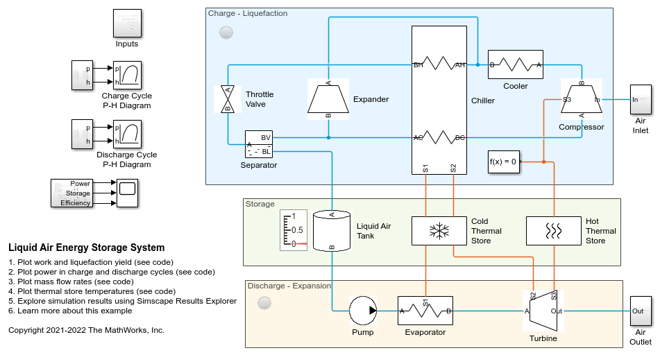
Liquid Air Energy Storage System
Models a grid-scale energy storage system based on cryogenic liquid air. When there is excess power, the system liquefies ambient air based on a variation of the Claude cycle. The cold liquid air is stored in a low-pressure insulated tank until needed. When there is high power demand, the system expands the stored liquid air to produce power based on the Rankine cycle.
Ports
Conserving
Input
Parameters
References
[1] ISO 6358-3. "Pneumatic fluid power – Determination of flow-rate characteristics of components using compressible fluids – Part 3: Method for calculating steady-state flow rate characteristics of systems". 2014.
[2] IEC 60534-2-3. "Industrial-process control valves – Part 2-3: Flow capacity – Test procedures". 2015.
[3] ANSI/ISA-75.01.01. "Industrial-Process Control Valves – Part 2-1: Flow capacity – Sizing equations for fluid flow underinstalled conditions". 2012.
[4] P. Beater. Pneumatic Drives. Springer-Verlag Berlin Heidelberg. 2007.