Pressure Relief Valve (TL)
Pressure relief valve in a thermal liquid network

Libraries:
Simscape /
Fluids /
Thermal Liquid /
Valves & Orifices /
Pressure Control Valves
Description
The Pressure Relief Valve (TL) block represents a valve that relieves excess pressure in a thermal liquid network. The valve remains closed when the pressure is less than a specified value. When this pressure is met or surpassed, the valve opens. This set pressure is either a threshold pressure differential over the valve, between ports A and B, or between port A and atmospheric pressure. A control pressure above the set pressure causes the valve to gradually open, which allows the fluid network to relieve excess pressure.
Pressure Control
The normalized pressure, , controls the valve opening area when Opening
parameterization is Linear - Area vs.
pressure. The normalized pressure is
where:
pcontrol is the control pressure, which depends on the value of the Pressure control specification parameter.
When you set Pressure control specification to
Pressure differential, the control pressure is pA ̶ pB.When you set Pressure control specification to
Pressure at port A, the control pressure is the difference between the pressure at port A and atmospheric pressure.pset is the set pressure, which depends on the value of the Pressure control specification parameter.
When you set Pressure control specification to
Pressure differential, pset is the value of the Set pressure differential parameter.When you set Set pressure specification to
Pressure at port A, pset is the value of the Set pressure (gauge) parameter.pmax is the maximum pressure, pmax = pset + prange, where prange is the value of the Pressure regulation range parameter.
Opening Parameterization
The mass flow rate depends on the value of the Opening parameterization parameter.
When you set Set pressure control to
Constant and Opening
parameterization to Linear - Area vs.
pressure or Tabulated data - Area vs.
pressure, the mass flow rate is
where:
Cd is the value of the Discharge coefficient parameter.
Avalve is the instantaneous valve open area.
Aport is the value of the Cross-sectional area at ports A and B parameter.
is the average fluid density.
Δp is the valve pressure difference pA – pB.
The critical pressure difference, Δpcrit, is the pressure differential associated with the Critical Reynolds number, Recrit, the flow regime transition point between laminar and turbulent flow:
where μ is the dynamic viscosity of the thermal liquid.
The pressure loss, PRloss, describes the reduction of pressure in the valve due to a decrease in area. The block calculates PRloss as
The pressure recovery describes the positive pressure change in the valve due to an increase in area. When you clear the Pressure recovery check box, the block sets PRloss to 1.
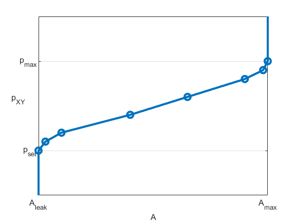
When you set Opening parameterization to
Linear - Area vs. pressure, the block calculates
the opening area as
where Aleak is the value of the Leakage Area parameter and Amax is the value of the Maximum opening area parameter.
This figure shows how the block controls the opening area using the linear parameterization.

When the valve is in a near-open or near-closed position in the linear parameterization, you can maintain numerical robustness in your simulation by adjusting the Smoothing factor parameter. If the Smoothing factor parameter is nonzero, the block smoothly saturates the control pressure between pset and pmax. For more information, see Numerical Smoothing.
When you set Opening parameterization to
Tabulated data - Area vs.
                        pressure
, the block
calculates the opening area as
where:
pcontrol,TLU,ref = pTLU + poffset.
pTLU is the Pressure differential vector or Opening pressure (gauge) vector parameter, depending on the value of the Pressure control specification parameter.
poffset is an internal pressure offset that causes the valve to start closing when pcontrol,TLU,ref = pset.
ATLU is the Opening area vector parameter.
This figure shows how the block controls the opening area when
Opening parameterization is Tabulated data
- Area vs. pressure.
When you set Set pressure control to
Constant and Opening
parameterization to Tabulated data - Volumetric flow
rate vs. pressure, the valve opens according to the
user-provided tabulated data of volumetric flow rate and pressure differential
between ports A and B.
The block calculates the mass flow rate as
where:
is the volumetric flow rate.
is the average fluid density.
The block calculates the relationship between the mass flow and pressure using
where
When you set Set pressure control to
Controlled, the control pressure is the pressure
differential between ports A and B and
there is no option to use a gauge pressure. The normalized pressure is
where:
ps is the value of the signal at port Ps.
pmax = ps + prange, where prange is the value of the Pressure regulation range parameter.
pcontrol is the pressure differential between ports A and B, pA ̶ pB.
Opening Dynamics
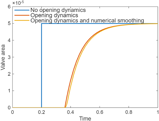
When you select Opening dynamics, the block applies a first-order filter to the valve area based on the Opening time constant parameter, τ. The valve area, Avalve, becomes the dynamic area, Adyn,
When you select Opening dynamics, the valve does not respond to changes instantaneously. This figure shows an example valve area in response to a step in the valve input pressure with and without opening dynamics:
When you clear Opening dynamics, the valve area mirrors the step change in the pressure at the input.
When you select Opening dynamics and set Opening time constant to
0.1 s, the valve area asymptotically approaches its limit.
Specifying a nonzero value for the Smoothing factor parameter provides additional numerical stability when the valve area is changing and in the near-closed or near-open position. For more information, see Numerical Smoothing.
Energy Balance
The energy conservation equation in the valve is
where:
ϕA is the energy flow rate into the valve through port A.
ϕB is the energy flow rate into the valve through port B.
Faults
To model a fault, in the Faults section, click the Add fault hyperlink next to the fault that you want to model. Use the fault parameters to specify the fault properties. For more information about fault modeling, see Introduction to Simscape Faults.
The Opening area when faulted parameter has three fault options:
Closed— The valve freezes at its smallest value:When you set Set pressure control to
Constantand Opening parameterization toLinear - Area vs. pressure, the valve area freezes at the Leakage area parameter.When you set Set pressure control to
Constantand Opening parameterization toTabulated data - Area vs. pressure, the valve area freezes at the first element of the Opening area vector parameter.When you set Set pressure control to
Controlledthe valve area freezes at the Leakage area parameter.
Open— The valve freezes at its largest value:When you set Set pressure control to
Constantand Opening parameterization toLinear - Area vs. pressure, the valve area freezes at the Maximum opening area parameter.When you set Set pressure control to
Constantand Orifice parameterization toTabulated data - Area vs. pressure, the valve area freezes at the last element of the Opening area vector parameter.When you set Set pressure control to
Controlledthe valve area freezes at the Maximum opening area parameter.
Maintain last value— The valve area freezes at the valve open area when the trigger occurred.
Due to numerical smoothing at the extremes of the valve area, the minimum area the block uses is larger than the Leakage area parameter, and the maximum is smaller than the Maximum orifice area parameter, in proportion to the Smoothing factor parameter value.
After the fault triggers, the valve remains at the faulted area for the rest of the simulation.
When you set Opening parameterization to
Tabulated data - Volumetric flow
                        rate vs. pressure
,
the fault options are defined by the volumetric flow rate through the valve:
Closed— The valve stops at the mass flow rate associated with the first elements of the Volumetric flow rate vector parameter and the Pressure drop vector parameter:Open— The valve stops at the mass flow rate associated with the last elements of the Volumetric flow rate vector parameter and the Pressure drop vector parameter:Maintain at last value— The valve stops at the mass flow rate and pressure differential when the trigger occurs:
where
Examples
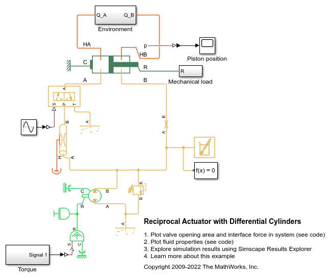
Reciprocal Actuator with Differential Cylinders
A double-acting actuator with differential cylinders. The pump output is connected to cylinder B of the actuator while cylinder A of the actuator can be connected to either the pump or the reservoir through the 3-way directional valve. When cylinder A is connected to the pump, pressures at both cylinders become equal. Because of the larger effective piston area in cylinder A, the interface force in cylinder A is larger than that of in cylinder B which causes the piston to extend. When cylinder A is connected to the reservoir, the piston starts to retract. The 3-way directional valve is controlled by a sinusoidal signal to achieve repeating reciprocal motion in the actuator.