Main Content

Temperature Control Valve (TL)

Temperature control valve in a thermal liquid network

  • Temperature Control Valve (TL) block

Libraries:
Simscape / Fluids / Thermal Liquid / Valves & Orifices / Flow Control Valves

Description

The Temperature Control Valve (TL) block models an orifice with a thermostat as a flow control mechanism. The thermostat contains a temperature sensor and a black-box opening mechanism—one whose geometry and mechanics matter less than its effects. The sensor responds with a slight delay, captured by a first-order time lag, to variations in temperature.

When the sensor reads a temperature in excess of a preset activation value, the opening mechanism actuates and the valve begins to open or close, depending on the operation mode specified by the Valve operation parameter. The change in opening area continues up to the limit of the temperature range of the valve, beyond which the opening area is a constant. Within the temperature range, the opening area is a linear function of temperature.

A smoothing function allows the valve opening area to change smoothly between the fully closed and fully open positions. The smoothing function does this by removing the abrupt opening area changes at the zero and maximum ball positions.

Mass Balance

The mass conservation equation in the valve is

m˙A+m˙B=0,

where:

  • m˙A is the mass flow rate into the valve through port A.

  • m˙B is the mass flow rate into the valve through port B.

Momentum Balance

The momentum conservation equation in the valve is

pApB=m˙m˙2+m˙cr22ρAvgCd2S2[1(SRS)2]PRLoss,

where:

  • pA and pB are the pressures at port A and port B.

  • m˙ is the mass flow rate.

  • m˙cr is the critical mass flow rate,

    m˙cr=RecrμAvgπ4SR.

  • ρAvg is the average liquid density.

  • Cd is the value of the Discharge coefficient parameter.

  • S is the value of the Cross-sectional area at ports A and B parameter.

  • SR is the valve opening area.

  • PRLoss is the pressure ratio,

    PRLoss=1(SR/S)2(1Cd2)Cd(SR/S)1(SR/S)2(1Cd2)+Cd(SR/S).

Energy Balance

The energy conservation equation in the valve is

ϕA+ϕB=0,

where:

  • ϕA is the energy flow rate into the valve through port A.

  • ϕB is the energy flow rate into the valve through port B.

Valve Opening Area

The valve opening area calculation is based on the linear expression

SLinear=(SEndSStartTRange)(TSensorTActivation)+SStart,

where:

  • SLinear is the linear valve opening area.

  • SStart is the valve opening area at the beginning of the temperature actuation range. This area depends on the Valve operation parameter setting:

    SStart={SLeak,Valve opens above activation temperatureSMax,Valve closes above activation temperature

  • SEnd is the valve opening area at the end of the temperature actuation range. This area depends on the Valve operation parameter setting:

    SEnd={SMax,Valve opens above activation temperatureSLeak,Valve closes above activation temperature

  • SMax is the value of the Maximum opening area parameter.

  • SLeak is the value of the Leakage area parameter.

  • TRange is the value of the Temperature regulation range parameter.

  • TActivation is the value of the Activation temperature parameter

  • TSensor is the sensor temperature reading.

    • When Temperature sensing is Valve inlet temperature, TSensor is the average temperature inside the valve.

    • When Temperature sensing is Thermal liquid sensing port, TSensor is the temperature of the thermal liquid network where it connects to port T.

    • When Temperature sensing is Thermal sensing port, TSensor is the temperature of the thermal network where it connects to port T.

The valve model accounts for a first-order lag in the measured valve temperature through the differential equation

ddt(TSensor)=TAvgTSensorτ,

where:

  • TAvg is the arithmetic average of the valve port temperatures,

    TAvg=TA+TB2,

    where TA and TB are the temperatures at ports A and B.

  • τ is the value of the Sensor time constant parameter.

When the valve is in a near-open or near-closed position you can maintain numerical robustness in your simulation by adjusting the Smoothing factor parameter. If the Smoothing factor parameter is nonzero, the block smoothly saturates the valve area between SLeak and SMax. For more information, see Numerical Smoothing.

Variables

To set the priority and initial target values for the block variables prior to simulation, use the Initial Targets section in the block dialog box or Property Inspector. For more information, see Set Priority and Initial Target for Block Variables.

Nominal values provide a way to specify the expected magnitude of a variable in a model. Using system scaling based on nominal values increases the simulation robustness. Nominal values can come from different sources, one of which is the Nominal Values section in the block dialog box or Property Inspector. For more information, see Modify Nominal Values for a Block Variable.

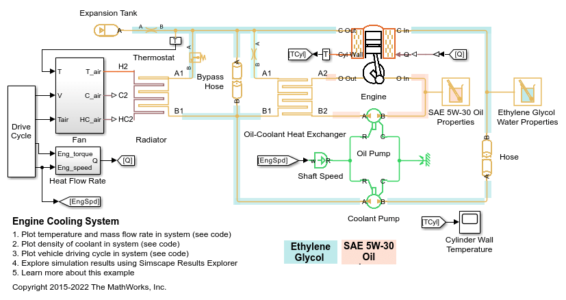
Examples

Ports

Conserving

expand all

Thermal liquid conserving port associated with the liquid entry or exit point to the valve.

Thermal liquid conserving port associated with the liquid entry or exit point to the valve.

Thermal liquid or thermal conserving port associated with temperature sensing. There is no mass or energy flow through this port. When Temperature sensing is Thermal liquid sensing port, port T is a thermal liquid sensing port. When Temperature sensing is Thermal sensing port, port T is a thermal sensing port.

Dependencies

To enable this port, set Temperature sensing to Thermal liquid sensing port or Thermal sensing port.

Parameters

expand all

Sign of the change in opening area induced by warming. The opening area can expand with a rise in temperature or it can contract. The change begins at an activation temperature and continues with warming conditions throughout the temperature regulation range of the valve.

The default setting corresponds to a normally closed valve that opens with rising temperature; the alternative setting corresponds to a normally open valve that closes with the same.

Method the block uses to measure the temperature that controls the valve:

  • When you set Temperature sensing to Valve inlet temperature, the valve uses the average fluid temperature inside the valve to control the valve.

  • When you set Temperature sensing to Thermal liquid sensing port, the block enables port T, which is a thermal liquid sensing port. Connect this port to a thermal liquid network to use that temperature to control the valve. The block only uses port T for sensing and it has no flow going in or out.

  • When you set Temperature sensing to Thermal sensing port, the block enables the thermal sensing port T. Connect this port to any part of a thermal network to use that temperature to control the valve. The block only uses port T for sensing and it has no heat exchange with the environment.

Temperature at which the opening mechanism triggers. Warming above this temperature will either open or close the valve, depending on the setting of the Valve operation parameter. The opening area remains variable throughout the temperature regulation range of the valve.

Temperature interval over which the valve opening area varies. The interval begins at the value of the Activation temperature parameter.

Characteristic time for a temperature change to register at the inlet sensor. This parameter determines the delay between the onset of a change and a stable measurement of the change. A value of 0 means that the sensor responds instantaneously to a temperature change.

Opening area of the valve in the fully open position, when the valve is at the upper limit of the pressure regulation range. The block uses this parameter to scale the valve opening throughout the pressure regulation range.

Sum of all gaps when the valve is in the fully closed position. Any area smaller than this value is saturated to the specified leakage area. This contributes to numerical stability by maintaining continuity in the flow.

Continuous smoothing factor that introduces a layer of gradual change to the flow response when the valve is in near-open or near-closed positions.

Areas at the entry and exit ports A and B, which are used in the pressure-flow rate equation that determines the mass flow rate through the orifice.

Correction factor accounting for discharge losses in theoretical flows.

Upper Reynolds number limit for laminar flow through the valve.

Extended Capabilities

C/C++ Code Generation
Generate C and C++ code using Simulink® Coder™.

Version History

Introduced in R2016a

expand all