Turbine (MA)
Libraries:
Simscape /
Fluids /
Moist Air /
Turbomachinery
Description
The Turbine (MA) block models a turbine in a moist air network. You can parameterize the block as a tabulated turbine map that is either a 1-D function of pressure ratio or 2-D function of pressure ratio and corrected mass flow rate. Fluid flowing from port A to port B generates torque. Port R reports shaft torque and angular velocity relative to port C, which represents the turbine casing.
When enabled, port VN represents the nozzle opening fraction.
This value linearly scales the corrected mass flow rate but does not influence the
turbine efficiency. A value of 1 corresponds to the data in the
turbine map.
Turbine Map
To visualize the block map, in the block dialog box, click the Plot button next to Turbine map. Each time you modify the block settings, click Reload Data on the figure window.
The turbine map relates turbine performance, as a function of pressure ratio, to the corrected mass flow rate and isentropic efficiency. The pressure ratio is the ratio between the turbine inlet pressure and outlet pressure.
The turbine map plots two separate graphs: corrected mass flow rate versus
pressure ratio and isentropic efficiency versus pressure ratio. When you set the
Turbine map parameterization to Tabulated
data - flow rate and efficiency vs. corrected speed and pressure
ratio, the plots also depend on the corrected rotor speed,
N. The indexing variable β does not need to be the same
between the mass flow rate and efficiency tables.
Due to the large changes in pressure and temperature inside a turbine, the turbine map plots performance in terms of the corrected mass flow rate.
The map adjusts the corrected mass flow rate from the inlet mass flow rate by using the reference pressure and reference temperature,
where:
ṁA is the mass flow rate at port A.
TA is the temperature at port A.
Tref is the value of the Reference temperature for corrected flow parameter.
RA is the mixture specific gas constant at port A.
Rref is the mixture specific gas constant calculated at the values of the Reference pressure for corrected flow, Reference temperature for corrected flow, and Reference relative humidity for corrected flow parameters.
γA is the ratio of specific heats at port A.
γref is the ratio of specific heats at the values of the Reference pressure for corrected flow, Reference temperature for corrected flow, and Reference relative humidity for corrected flow parameters.
pA is the pressure at port A.
pref is the value of the Reference pressure for corrected flow parameter.
The block also adjusts the shaft speed, ω, according to the reference temperature, such that the corrected shaft speed is
Shaft Torque
The block calculates the shaft torque, τ, as
where:
Δhtotal is the total change in the fluid specific enthalpy.
ηm is the value of the Mechanical efficiency parameter.
ω is the relative shaft angular velocity, ωR - ωC.
Reversed flow, from port B to port A, is outside of the typical turbine operation mode and may not return accurate results. A threshold region when flow approaches zero ensures the block generates no torque when the flow rate is near zero or reversed.
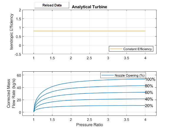
Analytical Parameterization
Use the analytical parametrization to create a turbine based on the expected
nominal operating conditions. When Turbine map parameterization
is Analytical – nominal pressure ratio and corrected mass flow
rate, the turbine isentropic efficiency is constant and the mass
flow rate is a function of the pressure ratio.
This image shows the default turbine map when you use the analytical parameterization.
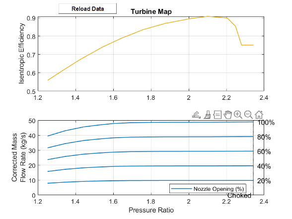
Parameterization by Pressure Ratio
When Turbine map parameterization is Tabulated
data - Flow rate and efficiency vs. pressure ratio, the turbine
isentropic efficiency and mass flow rate are a function of the pressure ratio and do
not account for any changes in the turbine rotational speed.
The last element of the Corrected mass flow rate vector, mdot(pr) and the Pressure ratio vector, pr parameters represents the corrected mass flow rate and pressure ratio at choked flow conditions.
This image shows the default turbine map when you use the 1-D parameterization.
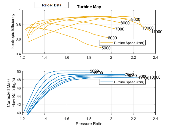
Parameterization by Pressure Ratio and Corrected Mass Flow Rate
When Turbine map parameterization is Tabulated
data - Flow rate and efficiency vs. corrected speed and pressure
ratio, the turbine isentropic efficiency, pressure ratio, and
corrected mass flow rate are a function of the corrected speed,
N, and the map index, β. The block uses linear
interpolation between data points for the efficiency, pressure ratio, and corrected
mass flow rate parameters.
The last column of the Corrected mass flow rate table, mdot(N,beta) and the Pressure ratio table, pr(N,beta) parameters represents the corrected mass flow rate and pressure ratio at choked flow conditions.
This image shows the default turbine map when you use the 2-D parameterization.
Conservation of Mass
When you clear the Model water vapor condensation parameter, the block conserves mass such that
where:
B is the mixture mass flow rate at port B.
wA and wB are the water vapor mass flow rates at ports A and B, respectively.
gA and gB are the trace gas mass flow rates at ports A and B, respectively.
dA and dB are the mass flow rates of the water droplets at ports A and B, respectively.
If you select Model water vapor condensation, the mass balance equations are
where γ is the value of the Fraction of condensate entrained as water droplets parameter.
The rate of water vapor condensation, wcond, is
xwcond is the mass fraction of water vapor that can condense,
where xwsB is the specific humidity at saturation and xwA is the specific humidity.
Conservation of Energy
When you clear the Model water vapor condensation parameter,
where:
ΦA is the energy flow rate at port A.
ΦB is the energy flow rate at port B.
Pfluid is the hydraulic power delivered to the fluid, which the block determines from the change in specific enthalpy, Δh,
If you select Model water vapor condensation, the block computes the energy balance equation as
where hdcond is the specific enthalpy of the water that is removed from the moist air flow by condensation.
Assumptions and Limitations
The shaft does not rotate under reversed flow conditions. Results during reversed flows may not be accurate.
Ports
Input
Output
Conserving
Parameters
Extended Capabilities
Version History
Introduced in R2025a