Hydraulic Axial-Piston Pump with Load-Sensing and Pressure-Limiting Control
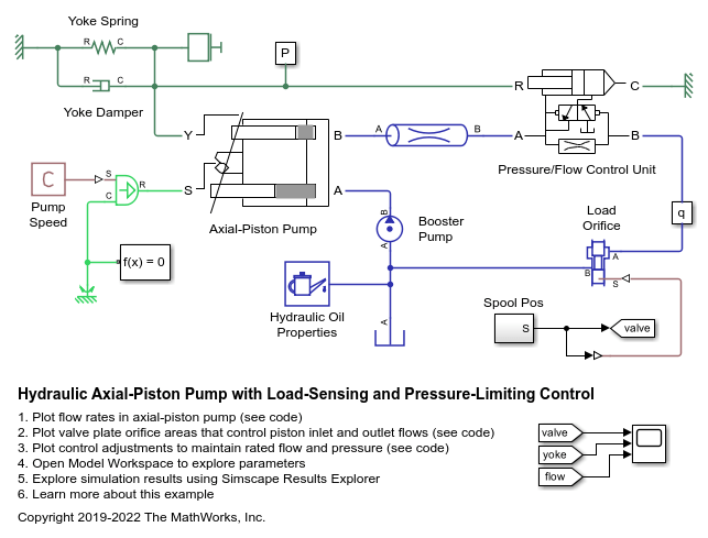
This example shows a test rig designed to investigate the interaction between an axial-piston pump and a typical control unit simultaneously performing the load-sensing and pressure-limiting functions. To increase the fidelity of the simulation, this example uses a detailed model of the pump that accounts for the interaction between the pistons, swash plate, and valve plate.
Model

Test Rig Description
The pump is modeled by the Axial-Piston Pump subsystem. The prime mover rotating the pump is represented by an angular velocity source. The pump's intake is connected to the output of a low pressure booster pump of 0.5 MPa. The pump output passes through a pipe, a control unit, and a variable orifice that acts as the load. To test the control unit's response to a variable load, the load orifice area is changed during simulation via the Spool Pos subsystem.
The control unit is modeled by the Pressure/Flow Control Unit subsystem. The load-sensing function of the pump control uses an orifice installed on the output flow path of the pump. The control unit keeps the pressure differential across this orifice constant regardless of the pump loading by adjusting the yoke displacement, which affects the tilt angle of the pump swash plate. This helps maintain the desired the flow rate through the orifice as well as prevent the pump pressure from exceeding the preset value.
The test rig basic parameters are:
Pump maximum displacement                        7.8877e-6 m^3/rad
Cylinder block pitch radius                      0.04 m
Piston diameter                                  0.015 m
Number of pistons                                5
Maximum piston stroke                            0.06 m
Swash plate maximum angle                        35 deg (0.6109 rad)
Arm length between the control actuator
  and the swash plate pivoting point             0.055 m
Swash plate control actuator stroke              0.04 m
Diameter of the orifice at the bottom
  of the piston chamber                          0.007 m
Pump maximum rated speed                         2500 RPM
Maximum pressure                                 27 MPa
Rated flow rate                                  1.1e-3 m^3/s
Axial-Piston Pump Subsystem
The pump under investigation has five pistons. Its schematic is shown below:

Figure 1: Axial-Piston Pump Schematic
where
- Valve plate (porting plate)
- Cylinder block (rotor)
- Piston
- Drive shaft
- Swash plate
The five pistons are modeled in the Axial-Piston Pump subsystem:

The pistons are identical and are modeled in their own identical subsystems. They are all connected to the following ports of the pump model:
S - Drive shaft
Y - Yoke connected with the inclined plate of the swash mechanism
A - Pump inlet (intake) port
B - Pump outlet (discharge) port
The yoke displacement is limited by a hard stop.
Piston Subsystem

The piston model consists of a Single-Acting Actuator (IL) block connected mechanically to the drive shaft via the Swash Plate block. The piston is also hydraulically connected to ports A and B via two Valve Plate Orifice (IL) blocks. Ports A and B represent the pump intake and discharge ports, respectively.
The piston sucks in liquid during its upstroke and expels liquid during its downstroke. The two Valve Plate Orifice (IL) blocks models the interaction between the fixed orifice at the bottom of the piston chamber and the two crescent-shaped grooves on the valve plate so that the piston is connected to port A during its upstroke and port B during its downstroke.
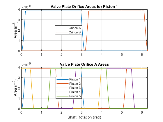
The following plot shows the flow areas formed by the interaction between the piston and the two crescent-shaped grooves on the valve plate. As the cylinder block rotates, the piston chamber orifice slides over the groove to open the flow area and then slides off the groove to close the flow area. The two grooves are separated by a phase angle of 180 degrees so that the piston slides over the groove connected to the intake (A) during the upstroke and slides over the groove connected to the discharge (B) during the downstroke. This results in the alternately open flow areas as shown in the first subplot.
The pistons are spread evenly along the pitch circle of the cylinder block, as shown in Figure 1. This makes the angle between pistons 360/5 = 72 degrees. Therefore, the phase angles of the Valve Plate Orifice (IL) blocks of each piston is offset from the previous piston by 72 degrees. This results in the evenly distributed and overlapping open flow areas for the intake groove as shown in the second subplot.

The tilt of the swash plate is what produces the piston motion as the cylinder block rotates. A Swash Plate block is connected to the Single-Acting Actuator (IL) to actuate that piston. Similar to the Valve Plate Orifice (IL) blocks, the phase angle of the Swash Plate block of each piston is offset from the previous piston by 72 degrees.
A greater swash plate angle results in larger piston motion which produces greater flow volume. The piston stroke must be long enough to allow the piston to reciprocate even at the maximum swash plate angle:

where  m is the pitch radius and
  deg is the maximum swash plate angle. This means the piston stroke must be greater than 0.056 m and is thus set to 0.06 m.
The piston initial positions must be equal to half of the stroke if the swash plate angle is zero. It is offset from half stroke depending on the phase angle of the piston if the initial swash plate angle is nonzero. The initial swash plate angle depends on the initial control actuator position. Therefore, the initial position of each piston is

where  is the swash plate control actuator initial position,
  is the swash plate control actuator arm, and
  is the phase angle of the piston in the cylinder block. This calculation is implemented in the Initialization tab of the Axial-Piston Pump subsystem mask.
Pressure/Flow Control Unit Subsystem
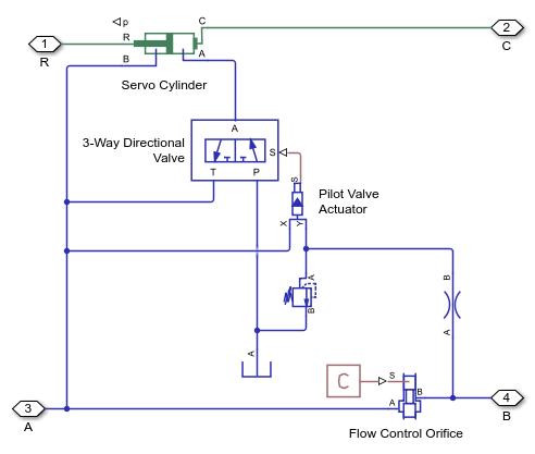
The purpose of the control unit is to implement two functions: load sensing and pressure limiting. Load sensing is implemented by maintaining a set pressure differential across a flow control orifice. The flow control orifice is installed in the output flow of the pump. The following figure shows the schematic of the control unit where the ports A and B are connected in series with the pump output.

Figure 2: Pressure/Flow Control Unit Schematic
The pressure before and after the flow control orifice acts on the side faces of the 3-way directional valve and shifts the valve spool proportionally to the pressure difference and the setting of the two centering springs. The valve connections are selected such that an increase in pressure differential across the flow control orifice opens the directional valve path P-A and closes path A-T. The control actuator is arranged as a single-rod differential hydraulic cylinder with the rod connected to the yoke of the swash plate. The pump displacement is increased if the rod moves in the positive direction shown in the schematic. Due to the difference in piston areas of the two sides of the cylinder, the displacement is increased if both cylinder chambers are connected to the pump and decreased if the chamber without the rod is connected to the tank. As a result, an increase in pressure differential across the flow control orifice causes the pump to decrease its displacement until it returns to the preset value.
The pressure-limiting function prevents the pump output pressure from exceeding the preset value. It is implemented with a pressure relief valve and a fixed orifice on the pressure line downstream of the flow control orifice. The pressure relief valve is set to the desired maximum value. When the pump pressure builds up to this value, the pressure relief valve opens to lower the pressure and causes the directional valve to increase path P-A decrease path A-T. This shifts the control actuator to decrease its displacement until pressure returns to the preset value.
The model of the control unit is shown below:

The control actuator is modeled with the Double-Acting Actuator (IL) block. The flow control orifice is modeled with the Spool Orifice (IL) block with the rectangular slot geometry option. The opening area of this orifice is chosen to give the desired rated flow rate of 1.1e-3 m^3/s for the load-sensing function.
The combination of the 3-Way Directional Valve (IL) block and the Pilot Valve Actuator (IL) block represents the directional valve in the schematic in Figure 2. Ports X and Y of the pilot valve senses the pressure acting on the two sides of the directional valve and adjusts the spool position of the 3-Way Directional Valve (IL) block. The centering springs in the Pilot Valve Actuator (IL) block returns the spool to the neutral position. Path A-T of the 3-Way Directional Valve (IL) block is set to be half open in the neutral position to force the pump to increase its displacement at the start of the operation. Other parameters such as spring stiffness, valve stroke, valve orifice areas, etc., are tuned in the model for accuracy and stability.
The set pressure differential in the pressure relief valve is set to 25 MPa. Since the load-sensing function maintains a roughly 2 MPa pressure difference across the flow control orifice, this causes the pressure-limiting function to maintain a maximum pressure of 27 MPa at port A of the control unit.
Test Rig Operation
The load of the test rig is represented by a Spool Orifice (IL) block. The simulation consists of six different loading conditions achieved by changing the spool position of the load orifice to 2 mm, 5 mm, 7 mm, 3 mm, 1 mm, and 4 mm. The control actuator initially increases the pump displacement to build up pressure. The process settles at around 0.35 s after the pressure difference across the flow control orifice becomes close to 2 MPa and the rated flow rate of 1.1e-3 m^3/s is achieved.
During the next three loading conditions, the control unit maintains the same pump delivery despite the varying load orifice opening.
At 1 s, the load orifice is almost closed, causing pump pressure to rise. The pressure-limiting function becomes dominant as the pressure reaches 27 MPa. The control unit returns to the load-sensing mode after the pressure falls below 27 MPa.
Simulation Results from Scopes

Simulation Results from Simscape Logging
This plot shows the flow rate within the axial-piston pump. The cyclic nature of the piston motion can be seen in the flow rate in each piston. The negative portion of the piston flow rate cycle corresponds to liquid being drawn in through valve plate A and the positive portion of the piston flow rate cycle corresponds to liquid being expelled through valve plate B. The combined effect of the five pistons results in the overall behavior of pump which produces a positive flow rate of about 1.1e-3 m^3/s through the load orifice.

This plot shows the load-sensing and pressure-limiting control. The pump maintains its rated flow rate of 1.1e-3 m^3/s even as the load varies. However, as the pump output pressure rises to its maximum rated pressure of 27 MPa, the pressure-limiting control decreases the yoke position and the flow rate drops below its rated flow rate.

