Hydraulic Oil System with Thermal Control
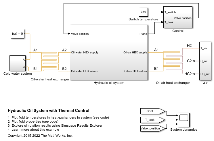
This example shows a hydraulic oil system with a thermal control using Simscape™ Fluids™ Thermal Liquid blocks. The hydraulic oil system consists of an oil storage tank represented by the Tank (TL) block with two inlets, a pump represented by a Mass Flow Rate Source (TL) block, and pipelines represented by Pipe (TL) block.
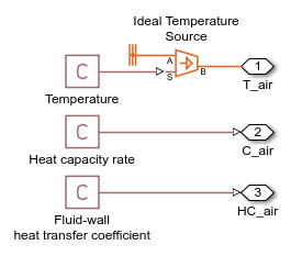
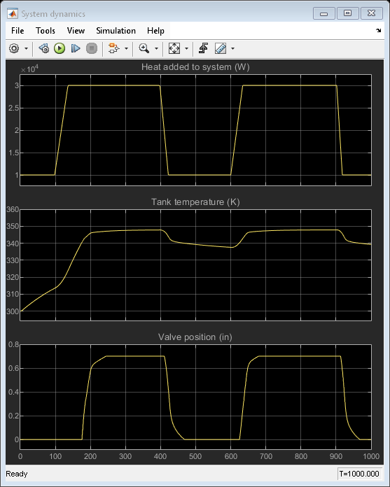
The system is subjected to intensive heating and as the result, the oil temperature in the tank keeps rising. To prevent the oil from overheating, the primary oil-air heat exchanger absorbs heat from the system. In the case when the oil-air heat exchanger cannot maintain the tank temperature below a threshold, the second oil-water heat exchanger is added to the system to further absorb heat. The oil-air heat exchanger is the E-NTU Heat Exchanger (TL) block with the air-side flow controlled by physical signal inputs. The flow of the oil into each heat exchanger is regulated through the 3-Way Directional Valve (TL) block.
Model

Hydraulic Oil Subsystem

Cold Water Subsystem

Air Subsystem

Simulation Results from Scopes

Simulation Results from Simscape Logging
These plots show the temperatures of hydraulic oil and water in the two heat exchangers. The oil-air heat exchanger primarily absorbs heat from the system. In the case when the oil temperature in the tank reaches a threshold, the 3-way directional valve diverts most of the flow to the oil-water heat exchanger to further lower the temperature.

Fluid Properties
This plots show the fluid properties of hydraulic oil and water as functions of pressure and temperature.

