Hydraulic Axial-Piston Motor
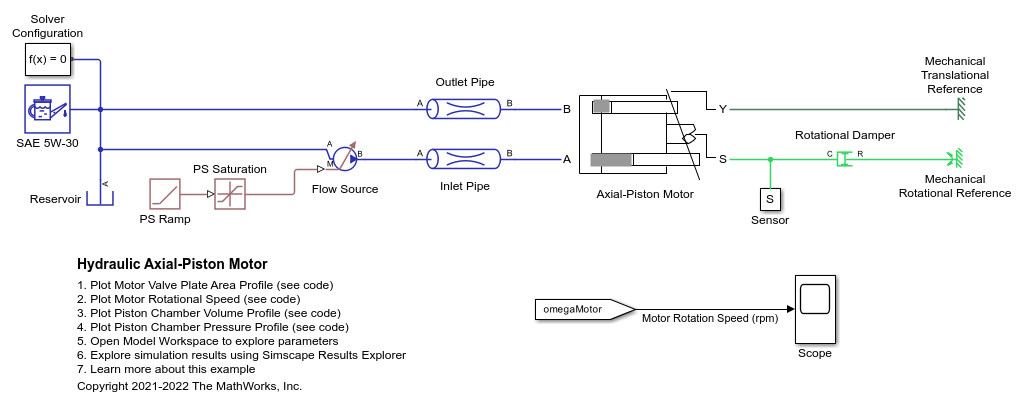
This example shows an axial piston motor with a test harness. To increase the fidelity of the simulation, this model uses a detailed representation of the motor that accounts for the interaction between the pistons, swash plate, and valve plate.
Model

Model Description
The Axial-Piston Motor subsystem contains the motor elements. The flow source connection at port A of the inlet pipe acts as the power source to the motor. The outlet pipe connects to the motor discharge at port B. The rotational damper acts as the load to the motor.
Axial-Piston Motor Subsystem
The five pistons are modeled in the Axial-Piston Motor subsystem:

The pistons are identical and are modeled in their own identical subsystems. They are all connected to the following ports of the motor model:
S - Motor output shaft
Y - Yoke connected with the inclined plate of the swash mechanism
A - Motor inlet (intake) port
B - Motor outlet (discharge) port
A Mechanical Translational Reference block keeps the yoke position constant.
Piston Subsystem

The piston model consists of a Single-Acting Actuator (IL) block connected mechanically to the drive shaft via the Swash Plate block. Two Valve Plate Orifice (IL) blocks hydraulically connect the piston to ports A and B. Ports A and B represent the motor intake and discharge ports, respectively.
The plot shows the flow area formation due to the piston and groove interaction.

The tilting of the swash plate causes piston motion as the cylinder block rotates. Each Swash Plate block also has a 72 degree offset.
Increasing the swash plate angle increases the volumetric flow per output shaft rotation. Note that the stroke length needs to accommodate for piston motion at the maximum swash plate angle.

where  m is the pitch radius and
  deg is the maximum swash plate angle. This means the piston stroke must be greater than 0.056 m. This example uses 0.06 m.
The plot shows how the valve plate area profiles correspond to the piston chamber volumes.

Simulation Results from Scope

Simulation Results from Simscape Logging
This plot shows the speed of rotation of the axial-piston motor. The speed is proportional to the inlet flow to the motor.

This plot shows in the first subplot the area profiles of the valve plate geometry. The second subplot shows the piston chamber pressure variation with respect to the cylinder block rotation.
