Refrigeration Cycle (System-Level)
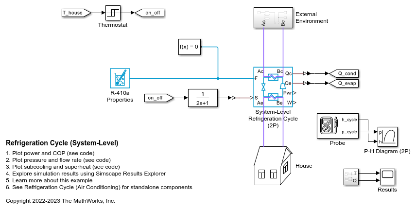
This example shows how to model a refrigeration cycle for a home air conditioning system at an abstract system level using the System-Level Refrigeration Cycle (2P) block. This block simplifies the set up of the refrigeration cycle by encapsulating the entire refrigerant loop in one block.
The System-Level Refrigeration Cycle (2P) block consists of several internal components. The evaporator absorbs heat from the air in the house and turns the refrigerant into a superheated vapor. The compressor then pressurizes and drives the refrigerant through the condenser, where the heat absorbed by the refrigerant and the compression work is rejected to the external environment. This causes the refrigerant to condense into a subcooled liquid which is then stored in the liquid receiver. The valve controls the amount of refrigerant that flows from the liquid receiver to the evaporator to maintain the desired amount of superheat. The valve also causes a drop in pressure which cools the refrigerant and allows it to absorb heat in the evaporator.
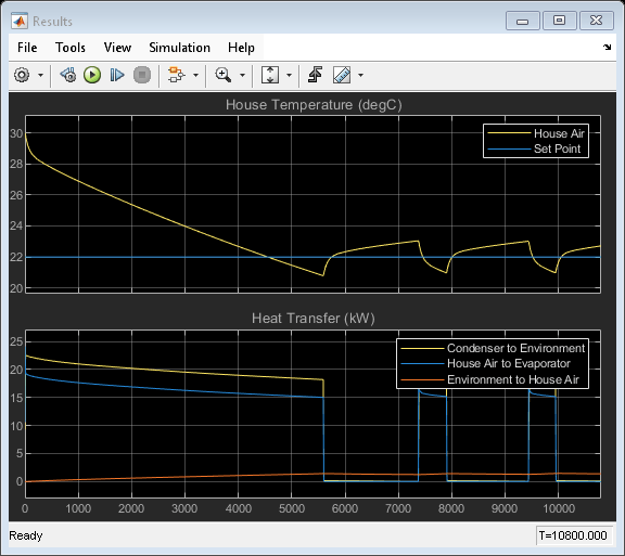
The cooling load in this model is the house, represented as a volume of air in the moist air domain. A thermal network models heat transfer between the hot external environment and the air in the house via the walls, roof, and windows. Additionally, occupants and appliances generate heat inside the house. A fan circulates air between the house and the evaporator for cooling. The system is controlled by a thermostat which turns the system on and off to maintain a temperature of 22 degC.
See the example Refrigeration Cycle (Air Conditioning) for how to model a refrigeration cycle using standalone components.
Model
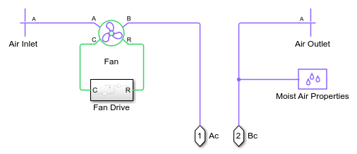
External Environment Subsystem
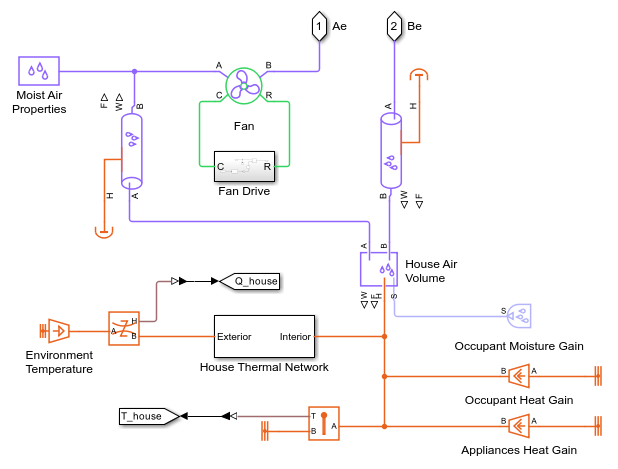
House Subsystem
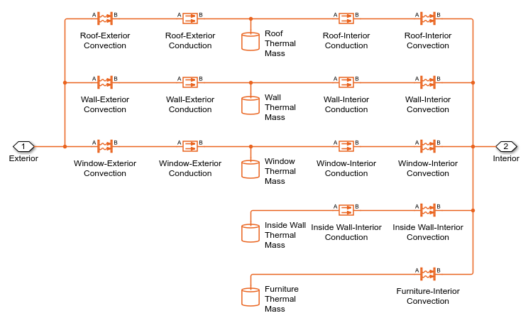
House Thermal Network Subsystem
Simulation Results from Scopes
Simulation Results from Simscape Logging
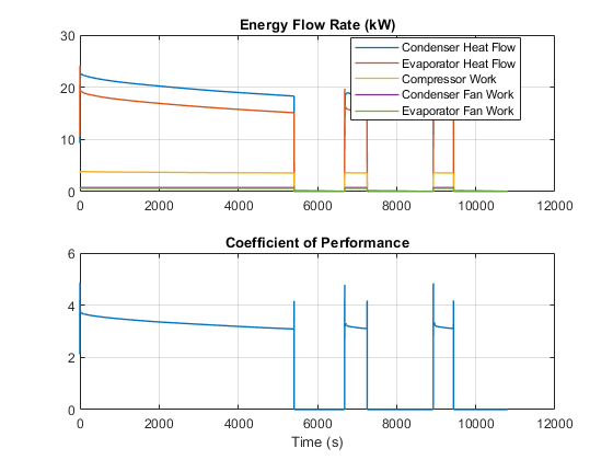
This plot shows the heat transfer in the condenser and the evaporator as well as the power consumed by the compressor and fans. The coefficient of performance is the ratio of the evaporator heat transfer to the total power consumed.
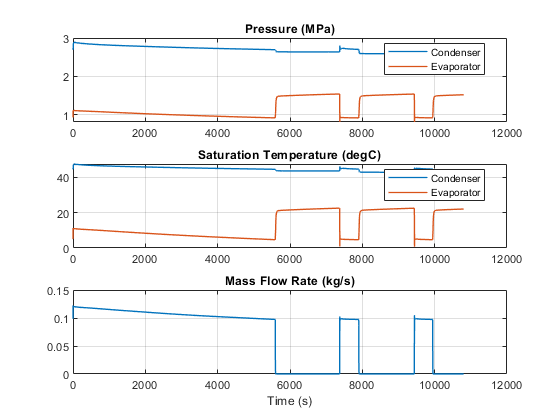
This plot shows the high and low pressure in the refrigeration cycle and the corresponding saturation temperatures. The design condensing temperature is 45 degC and the design evaporating temperature is 5 degC. The design refrigerant mass flow rate is around 0.1 kg/s.
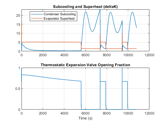
This plot shows the subcooling at the condenser outlet and the superheat at the evaporator outlet. The thermostatic expansion valve meters the flow into the evaporator in order to maintain a superheat of 5 degC.
See Also
System-Level Refrigeration Cycle (2P)