Control a PLC Using the Modbus Explorer
This example shows how to perform read and write operations to a PLC using the Modbus Explorer. The PLC is a Click Koyo cube with registers that can be used in industrial control and other industrial applications including controlling switches, timers, and sensors.
Open the Modbus Explorer. In the MATLAB Apps tab, under Test & Measurement, select Modbus Explorer.
The device is accessed over Serial RTU. To choose the communication interface in the Modbus Explorer click Device then Modbus Serial in the toolstrip.
On the Configure tab, configure the connection to your device by setting the following Serial RTU communication parameters in the toolstrip:
Port: Serial port Modbus® server is connected to. Set to COM4.Baud Rate: Bit transmission rate for serial port communication. The default is 9600 bits per seconds. Change it to 38400. Parity: Type of parity checking. Valid choices are none (default), even, and odd, and the actual required value is device-dependent. Set it to odd. Stop Bits: Number of bits used to indicate the end of data transmission. Valid choices are 1 (default) and 2, and the actual required value is device-dependent. Keep the default. Data Bits: Number of data bits to transmit. The default is 8, which is the Modbus standard for Serial RTU. Other valid values are 5, 6, and 7. Keep the default. Timeout: Maximum time in seconds to wait for a response from the Modbus server. The default is 3. You can edit the value to increase or decrease the timeout. Keep the default. Byte Order: Byte order of values written to or read from 16-bit registers. The default is Big Endian, as specified by the Modbus standard. Keep the default. Word Order: Word order for register reads and writes that span multiple 16-bit registers. The default is Big Endian, and it is device-specific. Set it to Little Endian. Configure the reading of data from your device by setting the following read parameters in the toolstrip:
Server ID: Address of the server to send the read command to, specified as a double. Valid values are 0-247, with 0 being the broadcast address. Set to 1. Register Type: Target area to read. You can perform a Modbus read operation on four types of targets: coils, inputs, input registers, and holding registers. Use the drop-down to select Coil. Register Address: Starting address to read from, specified as a double. Enter the number for your starting address, 16385in this case.Precision: Data format of the register being read from on the Modbus server. For coils and inputs, the precision is always bit. For holding registers and input registers, you can specify precisions such asuint16.The configuration should look like this after you configure the communication and read settings.

To test the configuration, click Read. If your configuration parameters are correct, the read is successful and the Read Value populates with the value from the read operation. If you get an error, adjust the parameters until the read is successful. In this case, the value should be 0.

After you have a correct read value, click Confirm Parameters. The Configure tab disappears and the Modbus Explorer tab appears, and your device is listed in the Device List on the left side of the app, as shown here.

You then use the table to set up more reads from your device. Fill in the Read Registers table to read data from two timers and three switches. Since the table automatically displays the register you configure in the Configure tab, the first timer is already listed. Change the name to
C1, then add four more rows so you have these reads set up.Switches C1, Address 16385, Coil, bit C2, Address 16386, Coil, bit C3, Address 16387, Coil, bit Timers T1, Address 45057, Holding Register, uint16 T2, Address 45058, Holding Register, uint16
The table should look like this:

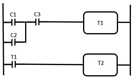
The PLC that contains these timers and switches is shown here.

To perform the reads on the five registers in the table, click Resume Reads.
The Read Value column displays the value that is returned and the status indicator changes to
LIVE, as shown here.
In this case, the value of 0 means the switch or timer is connected and available, but it is not activated.
To turn on one of the switches,
C1, perform a write to the register. In the Write Registers section, fill in the following:
After you have entered all of the fields, the Write button becomes activated.
To send the value to the register, click Write.
Since you have the same register listed in the Read Registers table, you see the read value update when you click Write. In the example shown here, you can see that the value of 1 was sent to the register and that it is now reflected in the read table for
C1, indicating that the switch is turned on.
Perform another write to turn the
C3switch on. In the Write Registers section, fill in the following:Address: 16387 Type: Coil Precision: bit Write Value: 1
Click Write.
Once that switch is on, the timers turn on, since that is how the PLC board is arranged.
T1is turned on when the switches are on, and then 5 seconds laterT2is automatically turned on. At that point both of the timers and two of the switches are turned on, as shown here.