Control Water pH Remotely Using Modbus Client Blocks in Simulink
This example shows how to use the Modbus Client Read and Modbus Client Write blocks in Simulink® to read and write sensor data from a Modbus server to regulate the pH level in a water treatment plant.
In a water treatment plant, monitor the plant status using sensors to check the pH level of the water, flow rate of primary pumps, and valve status of standby pumps. To optimize the pH level, when the detected value is not within the preferred range:
Control the flow rates of the primary acid and base pumps.
Activate the standby acid and base pumps when the pH level cannot be restored with primary pumps.
Trigger an alarm for manual intervention when the pH level is critically low or high and uncontrollable by both primary and standby pumps.
To control the pumps or trigger an alarm, provide control signals via actuators. For remote monitoring and control, connect the sensors and devices to a PLC which transmits and receives data over a Modbus network.
Prerequisites
Set up a Modbus TCP/IP server: To run this example in your MATLAB® session, you must install a Modbus® TCP/IP server on your local network.
Configure Modbus Client Read and Write blocks: To read or write data from a Modbus server, you must configure a Modbus client. For more information, see Configure Modbus Client in Simulink.
Model Description
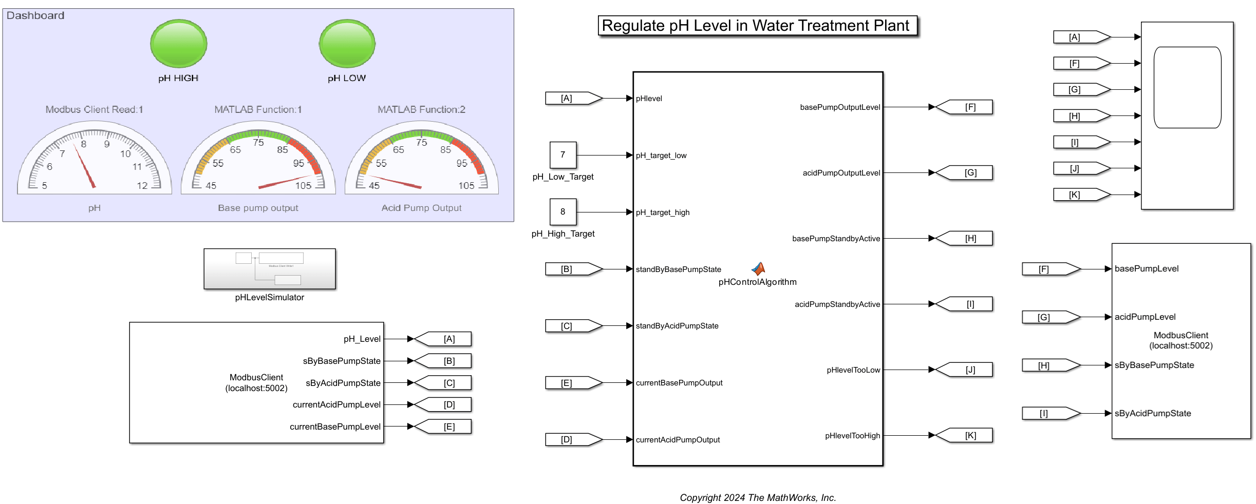
The WaterTreatmentPlant model provided with this example contains these blocks:
Subsystem block Generates pH sensor data and writes the data to a Modbus server. This block is labeled
pHLevelSimulator.Modbus Client Read block Reads sensor data from a Modbus TCP/IP server.
MATLAB Function block Processes the read data and generates control signals for the actuators based on user-defined thresholds. This block is labeled
pHControlAlgorithm.Modbus Client Write block Writes the control signals to corresponding registers on the Modbus server.
Dashboard and Scope blocks Visualizes the sensor data and control signals.
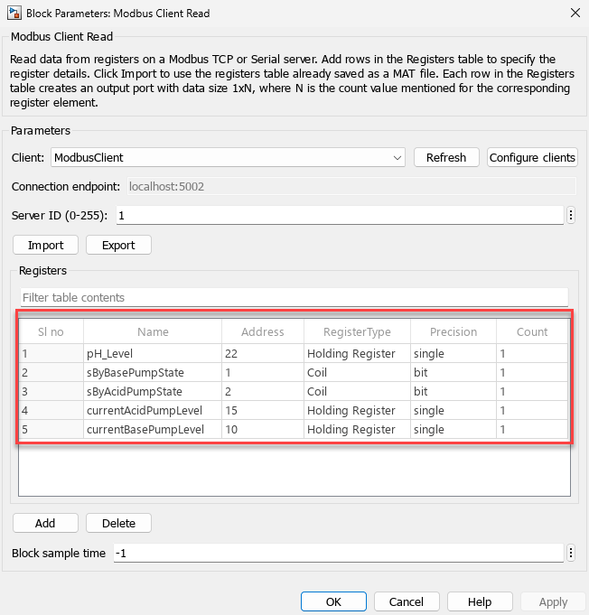
The image shows the parameter window of the Modbus Client Read block. For this example, the block reads data from five registers, which contain these values: current pH level of the water, flow rate of acid and base chemical pumps, and valve state of standby acid and base pumps.
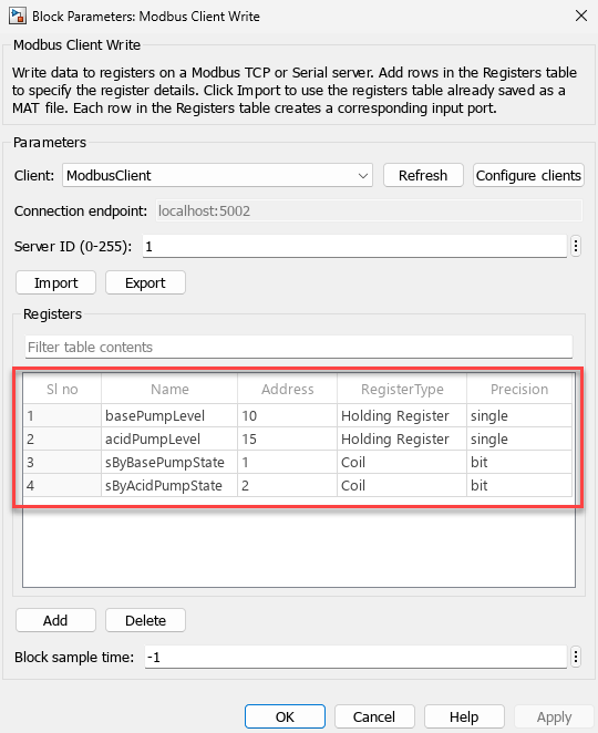
The image shows the parameter window of the Modbus Client Write block. For this example, the block writes data to four registers whose values can control these devices: primary acid and base pumps, and standby acid and base pumps.
The dashboard blocks visualize the current state of the water treatment plant. The Half Gauge (Simulink) blocks display the pH level of the water and flow rate of the primary pumps. The Lamp (Simulink) blocks show the status of the alarm, which is triggered when the pH level is critically low or high, indicating the need for manual intervention.
Understand Simulation Results
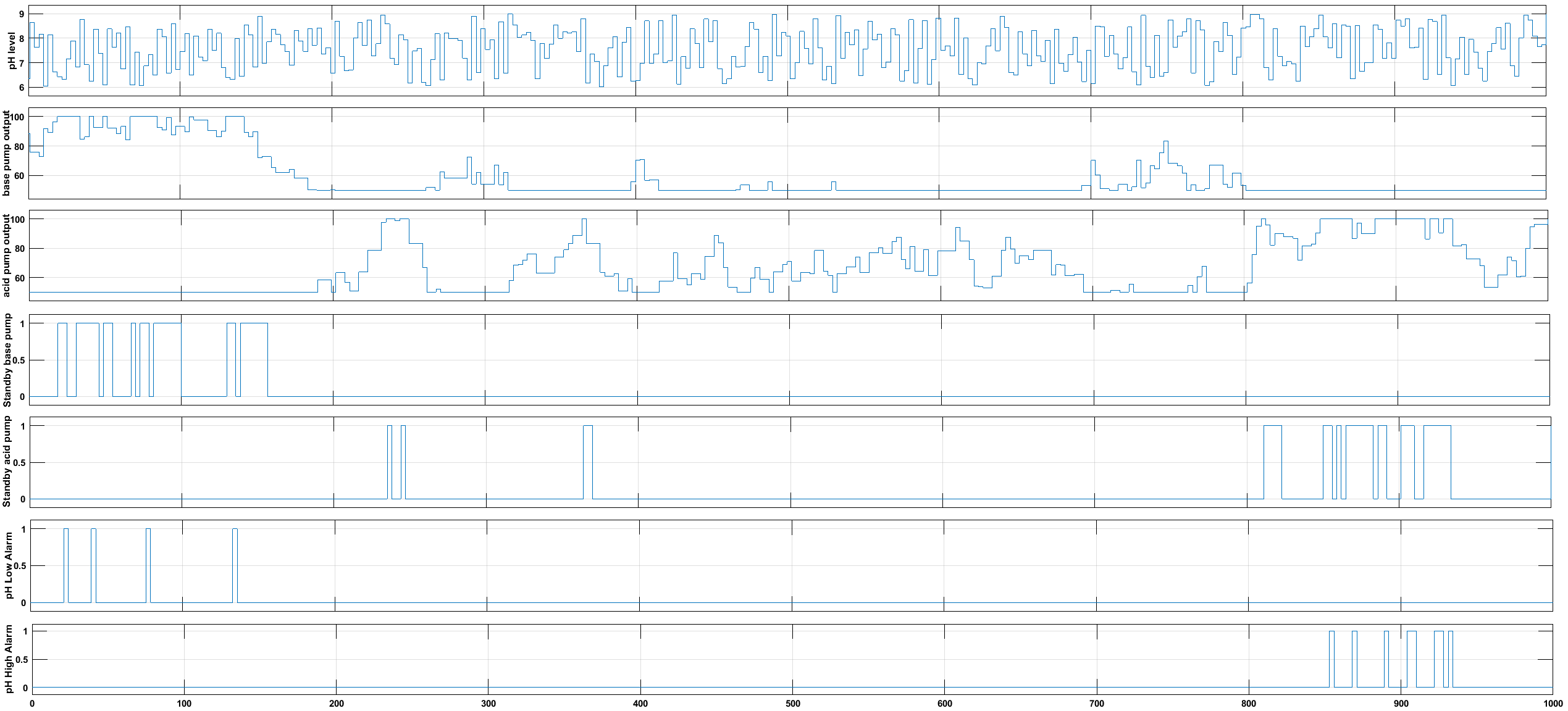
View the control signals and pH level sensor data using a Scope block. This example shows the pH variation from 6 to 9, flow rate variation of primary pumps from 50 to 100 , and the status of alarms and standby pumps as on or off.
For instance, if the pH level is above the optimal range of 7 to 8, to reduce the pH value, the base pump flow rate is decreased. The minimum value of the flow rate is defined as 50 . If the pH does not return to the optimal range even when the base pump flow rate reaches minimum, the acid pump flow rate is increased. The maximum value of the flow rate is defined as 100 . If the pH does not return to the optimal range even when the acid pump flow rate reaches maximum, the standby acid pump is turned on. When all these actions fail to restore the optimal pH, an alarm is triggered to indicate the need for manual intervention.
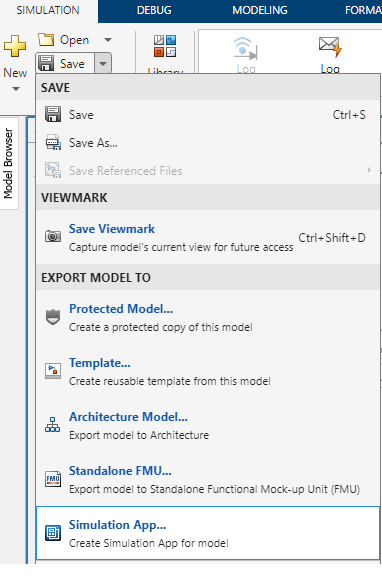
Create Simulation App for Model
Optionally, to generate a MATLAB app for the current model, on the Simulink toolstrip, under Save, select Export Model to Simulation App.
Note: You must install Simulink® Compiler to enable this option.
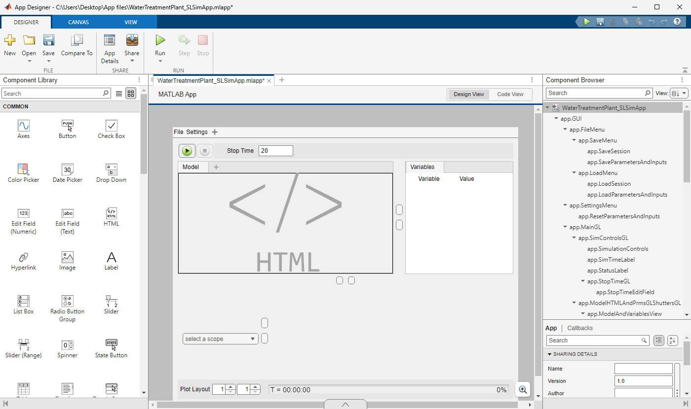
The image shows the Simulation App (MLAPP file) generated for the current model.
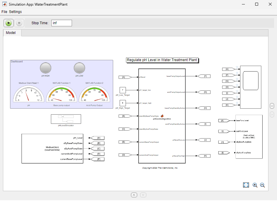
You can customize and share the app using the App Designer. For more information, see Generate, Modify, and Deploy a MATLAB App for a Simulink Model (Simulink Compiler).
