使用 Simulink 数据进行连续时间模型建模
此示例说明了如何使用 System Identification Toolbox™ 识别在 Simulink® 中仿真的模型。该示例阐述了如何处理连续时间系统与延迟,同时强调了输入信号采样间行为的重要性。
从 Simulink 模型获取仿真数据
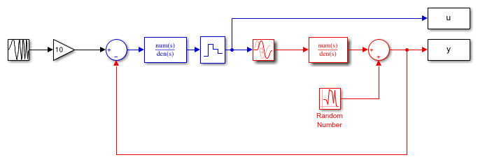
考虑由以下 Simulink 模型描述的系统:
open_system('iddemsl1')
set_param('iddemsl1/Random Number','seed','0')

红色部分是系统,蓝色部分是控制器,参考信号为扫频正弦波(即啁啾信号)。数据采样时间设置为 0.5 秒。
该系统可使用 idpoly 结构表示:
m0 = idpoly(1,0.1,1,1,[1 0.5],'Ts',0,'InputDelay',1,'NoiseVariance',0.01)
m0 =
Continuous-time OE model: y(t) = [B(s)/F(s)]u(t) + e(t)
  B(s) = 0.1

  F(s) = s + 0.5

Input delays (listed by channel): 1
Parameterization:
   Polynomial orders:   nb=1   nf=1   nk=0
   Number of free coefficients: 2
   Use "polydata", "getpvec", "getcov" for parameters and their uncertainties.

Status:
Created by direct construction or transformation. Not estimated.
让我们仿真模型 iddemsl1,并将数据保存到 iddata 对象中:
sim('iddemsl1')
dat1e = iddata(y,u,0.5); % The IDDATA object
让我们进行第二次模式仿真以进行验证。
set_param('iddemsl1/Random Number','seed','13')
sim('iddemsl1')
dat1v = iddata(y,u,0.5);
让我们来看看首次仿真中获得的估计数据:
plot(dat1e)

基于仿真数据的离散建模
让我们先评估一个默认阶数的离散模型,以初步了解数据特征:
m1 = n4sid(dat1e, 'best') % A default order model
m1 =
  Discrete-time identified state-space model:
    x(t+Ts) = A x(t) + B u(t) + K e(t)
       y(t) = C x(t) + D u(t) + e(t)

  A =
            x1       x2       x3
   x1   0.7881   0.1643  -0.1116
   x2  -0.1214   0.4223   0.8489
   x3   -0.155  -0.7527   0.2119

  B =
               u1
   x1  -0.0006427
   x2    -0.02218
   x3    -0.07347

  C =
           x1      x2      x3
   y1  -5.591   0.871  -1.189

  D =
       u1
   y1   0

  K =
              y1
   x1  -0.001856
   x2   0.002363
   x3    0.06805

Sample time: 0.5 seconds

Parameterization:
   FREE form (all coefficients in A, B, C free).
   Feedthrough: none
   Disturbance component: estimate
   Number of free coefficients: 18
   Use "idssdata", "getpvec", "getcov" for parameters and their uncertainties.

Status:
Estimated using N4SID on time domain data "dat1e".
Fit to estimation data: 86.17% (prediction focus)
FPE: 0.01281, MSE: 0.01251
检查模型对验证数据的复现效果。
compare(dat1v,m1)

如所观察,模型对验证数据的预测效果良好。为深入探究数据特征,让我们检查使用 dat1e 计算的非参数脉冲响应,其中分析所需的负滞后项将自动确定:
ImpModel = impulseest(dat1e,[],'negative');
clf
h = impulseplot(ImpModel);
showConfidence(h,3)

ImpModel 是一种其阶数(系数个数)自动确定的 FIR 模型。我们还选择通过计算负延迟的脉冲响应来分析反馈效应。负滞后效应的影响并非都微不足道。这是由于调节器(输出反馈)造成的。这意味着无法利用冲激响应估计值来确定时间延迟。相反,构建多个具有不同延迟的低阶 ARX 模型,并找出最佳拟合方案:
V = arxstruc(dat1e,dat1v,struc(1:2,1:2,1:10));
nn = selstruc(V,0) %delay is the third element of nn
nn =

     2     2     3
延迟被确定为 3 个滞后。(此处正确:1 秒的死区时间会产生两个滞后延迟,而 ZOH 模块还会产生另一个。)相应的 ARX 模型也可按以下方式计算:
m2 = arx(dat1e,nn)
compare(dat1v,m1,m2);
m2 =
Discrete-time ARX model: A(z)y(t) = B(z)u(t) + e(t)
  A(z) = 1 - 0.2568 z^-1 - 0.3372 z^-2

  B(z) = 0.04021 z^-3 + 0.04022 z^-4

Sample time: 0.5 seconds

Parameterization:
   Polynomial orders:   na=2   nb=2   nk=3
   Number of free coefficients: 4
   Use "polydata", "getpvec", "getcov" for parameters and their uncertainties.

Status:
Estimated using ARX on time domain data "dat1e".
Fit to estimation data: 85.73% (prediction focus)
FPE: 0.01346, MSE: 0.0133

优化估计
在仿真中,m1 和 m2 这两个模型表现相似。现在让我们尝试调整订单和延迟。将延迟固定为 2(结合无馈通特性,将产生 3 个采样点的净延迟),并以此延迟建立默认的序列状态空间模型:
m3 = n4sid(dat1e,'best','InputDelay',2,'Feedthrough',false);
% Refinement for prediction error minimization using pem (could also use
% |ssest|)
m3 = pem(dat1e, m3);
让我们来看看估计的系统矩阵。
m3.a % the A-matrix of the resulting model
ans =

    0.7332   -0.3784    0.1735
    0.4705    0.3137   -0.6955
   -0.0267    0.7527    0.6343
系统自动选择三阶动力学模型,结合两个"额外"延迟,形成五阶状态空间模型。
切勿盲目依赖自动订单选择,这始终是明智之举。它们受到随机误差的影响。一种有效的方法是观察模型的零点和极点,同时结合置信边界:
clf
h = iopzplot(m3);
showConfidence(h,2) % Confidence region corresponding to 2 standard deviations

显然单位圆上的两个极点/零点似乎相互抵消,这表明一阶动力学模型可能已足够。利用这些信息,让我们进行一次新的第一阶估计:
m4 = ssest(dat1e,1,'Feedthrough',false,'InputDelay',2,'Ts',dat1e.Ts);
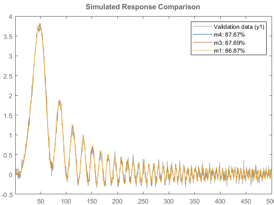
compare(dat1v,m4,m3,m1)

compare 图显示,简单的线性模型 m4 对数据具有极佳的拟合效果。因此我们将选择该模型作为最终结果。
离散模型向连续时间(线性时不变)模型的转换
将该模型转换为连续时间形式,并用传递函数表示:
mc = d2c(m4);
idtf(mc)
ans =

  From input "u1" to output "y1":
               0.09828
  exp(-1*s) * ----------
              s + 0.4903

Continuous-time identified transfer function.

Parameterization:
   Number of poles: 1   Number of zeros: 0
   Number of free coefficients: 2
   Use "tfdata", "getpvec", "getcov" for parameters and their uncertainties.

Status:
Created by direct construction or transformation. Not estimated.
如上所示,已获得该系统的良好描述。
直接估计连续时间模型
连续时间模型也可以直接进行估计。离散模型 m4 具有 2 个采样输入延迟,这代表 1 秒的延迟。我们使用 ssest 命令进行此估计:
m5 = ssest(dat1e,1,'Feedthrough',false,'InputDelay',1);
present(m5)
m5 =
  Continuous-time identified state-space model:
      dx/dt = A x(t) + B u(t) + K e(t)
       y(t) = C x(t) + D u(t) + e(t)

  A =
                         x1
   x1  -0.4903 +/- 0.008489

  B =
                          u1
   x1  0.01345 +/- 1.371e+11

  C =
                       x1
   y1  7.307 +/- 7.45e+13

  D =
       u1
   y1   0

  K =
                           y1
   x1  -0.02227 +/- 2.271e+11

  Input delays (seconds): 1

Parameterization:
   FREE form (all coefficients in A, B, C free).
   Feedthrough: none
   Disturbance component: estimate
   Number of free coefficients: 4
   Use "idssdata", "getpvec", "getcov" for parameters and their uncertainties.

Status:
Termination condition: Near (local) minimum, (norm(g) < tol)..
Number of iterations: 9, Number of function evaluations: 128

Estimated using SSEST on time domain data "dat1e".
Fit to estimation data: 87.34% (prediction focus)
FPE: 0.01054, MSE: 0.01047
More information in model's "Report" property.
不确定性分析
尽管模型 m5 与数据拟合度达 87%,其参数仍存在高度不确定性。这是因为该模型使用的参数数量超过了绝对必要值,导致参数估计的唯一性丧失。要观察模型中不确定性的真实影响,有两种可能的方法:
将不确定性视为模型响应的置信边界,而非参数的置信边界。
估计规范形式下的模型。
我们来试试这两种方法。首先,我们以规范形式估计模型。
m5Canon = ssest(dat1e,1,'Feedthrough',false,'InputDelay',1,'Form','canonical');
present(m5Canon)
m5Canon =
  Continuous-time identified state-space model:
      dx/dt = A x(t) + B u(t) + K e(t)
       y(t) = C x(t) + D u(t) + e(t)

  A =
                         x1
   x1  -0.4903 +/- 0.007881

  B =
                         u1
   x1  0.09828 +/- 0.001559

  C =
       x1
   y1   1

  D =
       u1
   y1   0

  K =
                        y1
   x1  -0.1628 +/- 0.03702

  Input delays (seconds): 1

Parameterization:
   CANONICAL form with indices: 1.
   Feedthrough: none
   Disturbance component: estimate
   Number of free coefficients: 3
   Use "idssdata", "getpvec", "getcov" for parameters and their uncertainties.

Status:
Termination condition: Near (local) minimum, (norm(g) < tol)..
Number of iterations: 9, Number of function evaluations: 128

Estimated using SSEST on time domain data "dat1e".
Fit to estimation data: 87.34% (prediction focus)
FPE: 0.01054, MSE: 0.01047
More information in model's "Report" property.
m5Canon 采用模型的规范参数化形式。它与估计数据以及模型 m5 同样吻合。它显示其参数值的微小不确定性,这证明了其可靠性。然而,正如我们在 m5 中看到的那样,较大的不确定性并不一定意味着模型“不好”。为验证这些模型的质量,让我们观察其在时域和频域中的响应,并标注出对应 3 个标准差的置信边界。我们还绘制了原始系统 m0 以供比较。
波特图。
clf
opt = bodeoptions;
opt.FreqScale = 'linear';
h = bodeplot(m0,m5,m5Canon,opt);
showConfidence(h,3)
legend show

阶跃图。
clf
showConfidence(stepplot(m0,m5,m5Canon),3)
legend show

两种模型的置信边界几乎完全一致。我们同样可以为这些模型生成带置信区域的极点零点图 (iopzplot) 和奈奎斯特图 (nyquistplot)。
idtf(m5)
ans =

  From input "u1" to output "y1":
               0.09828
  exp(-1*s) * ----------
              s + 0.4903

Continuous-time identified transfer function.

Parameterization:
   Number of poles: 1   Number of zeros: 0
   Number of free coefficients: 2
   Use "tfdata", "getpvec", "getcov" for parameters and their uncertainties.

Status:
Created by conversion from idss model.
连续时间估计中样本间行为的建模
在比较由采样数据计算得到的连续时间模型时,必须考虑输入信号的采样间行为。在迄今为止的示例中,由于控制器中的零阶保持 (ZOH) 电路,系统输入呈分段常数特性。现在移除这个电路,考虑一个真正的连续系统。输入和输出信号仍以 2 Hz 采样,其余所有参数均保持不变:
open_system('iddemsl3')
sim('iddemsl3')
dat2e = iddata(y,u,0.5);

离散时间模型在这些数据上仍能表现良好,因为当它们根据测量值进行调整时,将同时包含采样属性与当前输入的采样间输入行为。然而,在构建连续时间模型时,了解采样间属性至关重要。首先建模,就像 ZOH 案例那样:
m6 = ssest(dat2e,1,'Feedthrough',false,'InputDelay',1,'Form','canonical');
idtf(m6)
ans =

  From input "u1" to output "y1":
                0.1117
  exp(-1*s) * ----------
              s + 0.5597

Continuous-time identified transfer function.

Parameterization:
   Number of poles: 1   Number of zeros: 0
   Number of free coefficients: 2
   Use "tfdata", "getpvec", "getcov" for parameters and their uncertainties.

Status:
Created by conversion from idss model.
让我们将估计模型 (m6) 与真实模型 (m0) 进行比较:
step(m6,m0) % Compare with true system

该协议现在不太理想。然而,我们可以在数据对象中包含有关输入的信息。作为近似描述,可将其视为在采样时间点之间呈分段线性(一阶保持,FOH)。该信息随后被估计器用于适当的采样:
dat2e.Intersample = 'foh';
m7 = ssest(dat2e,1,'Feedthrough',false,'InputDelay',1,'Form','canonical');  % new estimation with correct intersample behavior
idtf(m7)
ans =

  From input "u1" to output "y1":
               0.09937
  exp(-1*s) * ----------
              s + 0.4957

Continuous-time identified transfer function.

Parameterization:
   Number of poles: 1   Number of zeros: 0
   Number of free coefficients: 2
   Use "tfdata", "getpvec", "getcov" for parameters and their uncertainties.

Status:
Created by conversion from idss model.
让我们再次看看阶跃响应的比较:
step(m7,m0) % Compare with true system

该模型 (m7) 的性能远优于 m6。本示例到此结束。
bdclose('iddemsl1');
bdclose('iddemsl3');