Visualizing Signal Data and 5G Wireless Measurements in an App
This example shows how to generate, transmit, and receive a test 5G waveform by communicating with instruments from MATLAB®. The example also shows how to visualize and analyze the waveform using an app that was created with App Designer.
Instrument Control Toolbox™ lets users connect MATLAB to instruments such as RF signal generators, spectrum analyzers and enables them to perform 5G wireless measurements.
In this example, you:
Generate a 5G NR-TM waveform using the 5G Waveform Generator.
Download and transmit the waveform onto a Keysight RF Signal Generator.
Receive the waveform using a Keysight Signal Analyzer.
Visualize and analyze the waveform using the
DataVisualization5GMeasurementapp provided with the example.

Requirements
To run the example app, you need:
MATLAB 2023a or later
Instrument Control Toolbox
5G Toolbox
Keysight® IO Libraries suite 2022 or newer
Keysight RF Signal Generator
Keysight Signal Analyzer
Generate Baseband Waveform
The 5G Waveform Generator app enables you to generate, impair, visualize, and transmit 5G NR waveforms. For more information, see 5G Waveform Generator (5G Toolbox).
In the MATLAB desktop, on the Apps tab, select 5G Waveform Generator.
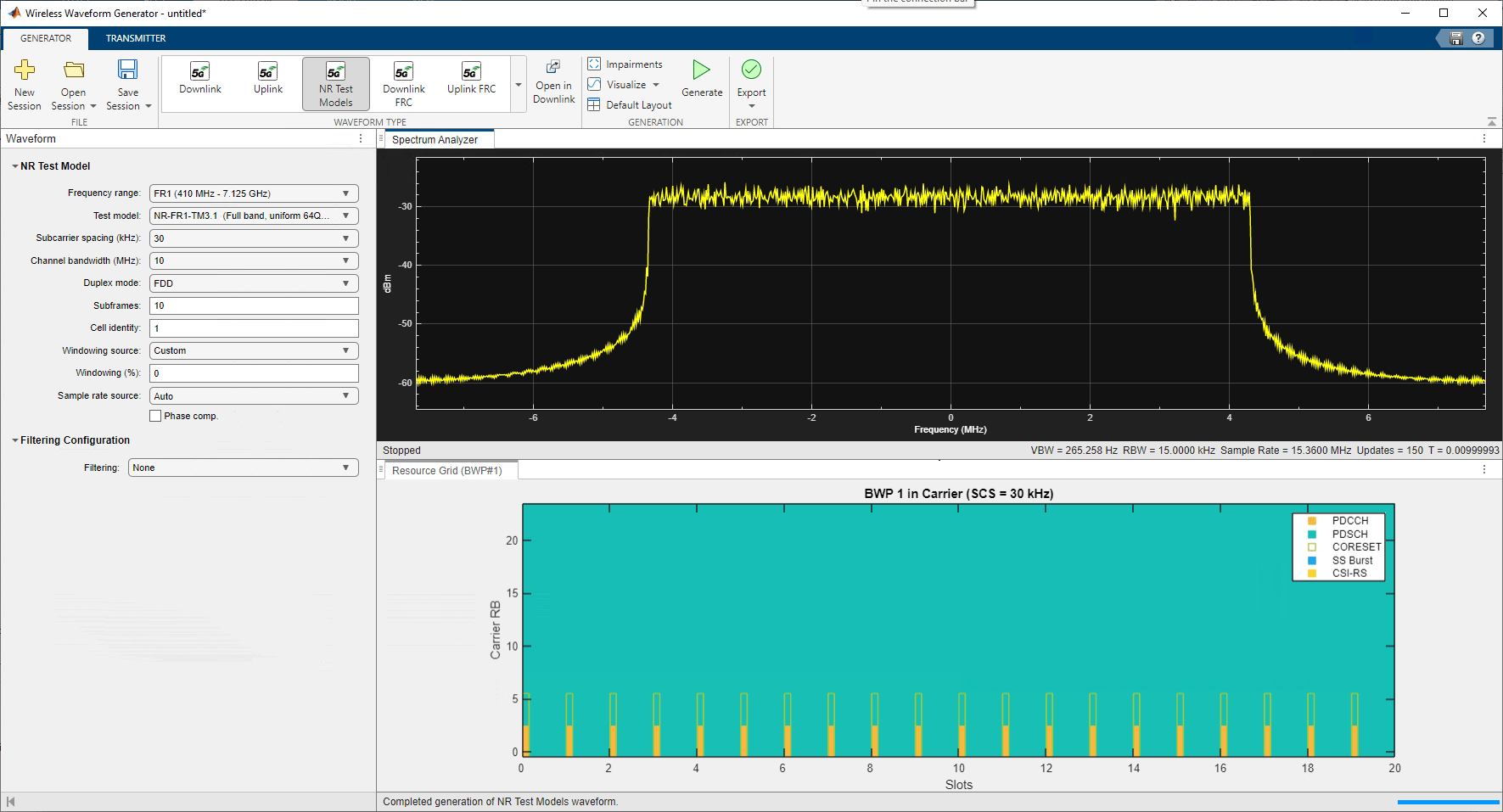
To specify the parameters of the waveform, in the Waveform Type section, select NR Test Models. In the left-most pane of the app, set the parameters for the waveform you want to transmit. For this example, use the following values:
Frequency range —
FR1 (410 MHz - 7.125 GHz)Test model —
NR-FR1-TM3.1 (Full band, uniform 64 QAM)Channel bandwidth (MHz) —
10Subcarrier spacing (kHz) —
30Duplex mode —
FDDSubframes —
10
Then generate the waveform by clicking Generate.

Transmit Over-the-Air Signal
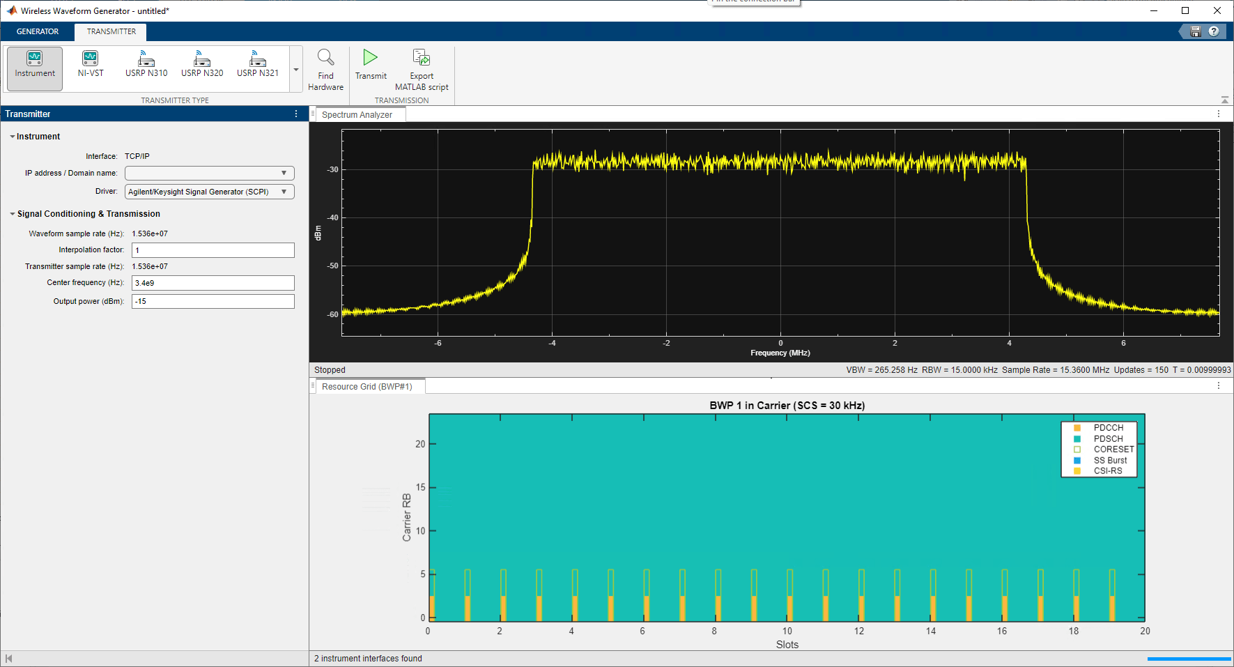
Download the generated signal to the RF signal generator over a supported communication interface. This example assumes that the RF signal generator is connected over the TCP/IP interface. 5G Waveform Generator automatically finds this connection. On the Transmitter tab of the app, in the Driver list, select Agilent/Keysight Signal Generator SCPI. For this example, set the Center frequency (Hz) parameter to 3.4e9 and the Output power (dBm) parameter to -15. The app automatically obtains the baseband sample rate from the generated waveform.
To start the transmission, click Transmit in the toolstrip.

Capture RF Signal
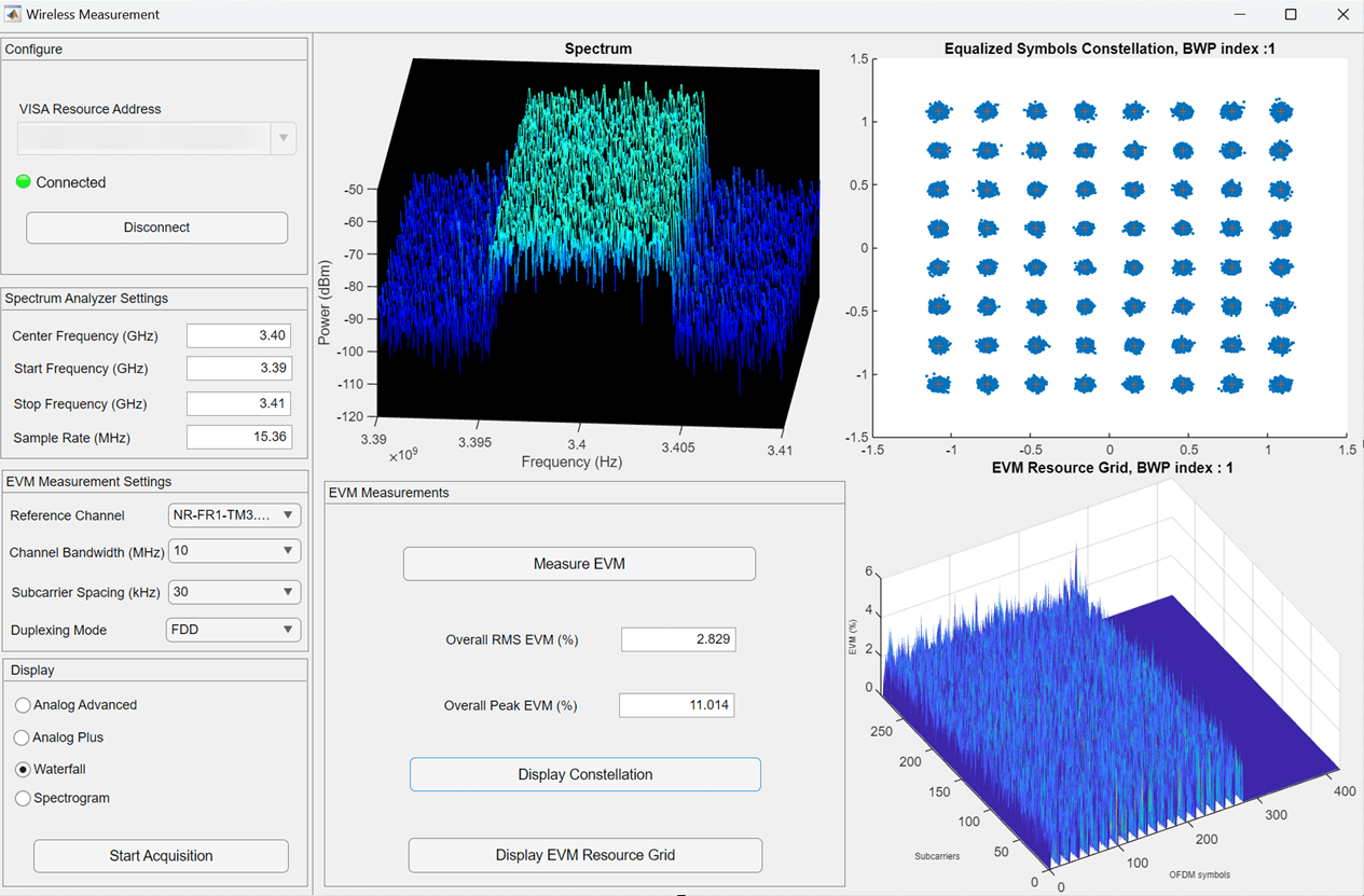
To visualize the signal, use the Data Visualization and Wireless Measurement app, created using App Designer. The app consists of a spectrum display for visualization and analysis of the 5G signal and also enables you to perform wireless measurements such as measuring the Overall EVM, Peak EVM and display constellation and EVM resource grid of the signal.

To access this app, open App Designer by running appdesigner at the command prompt. Click Open on the App Designer Start Page, navigate to the folder containing DataVisualization5GMeasurement.mlapp file, and open the file. Click Run to launch the app.
The app populates the VISA Resource Address drop-down list with the addresses of instruments connected to your computer. Select the VISA resource address of the Keysight spectrum analyzer and click Connect. A green dot indicates a successful connection.
Configure the spectrum analyzer settings. Because this example uses a 5G NR-TM waveform with a center frequency of 3.4 GHz and sample rate of 15.36 MHz, specify these settings:
Center Frequency — 3.4 GHz
Start Frequency — 3.39 GHz
Stop Frequency — 3.41 GHz
Sample Rate — 15.36 MHz
For the EVM Measurement settings, select the following values:
Reference Channel — NR-FR1-TM3.1 (Full band, uniform 64 QAM)
Channel Bandwidth — 10 MHz
Subcarrier Spacing — 30 kHz
Duplexing mode — FDD
Display Signal Spectrum
The plot displays the power spectrum of a received signal, which is the distribution of power in the signal as a function of frequency measured in dBm/Hz. In the Display section, select a mode of the power-spectrum plot.
Analog Advanced — Display signal using a color graded-persistence format. For example, a signal changes from blue to red the longer the signal remains at a given frequency.
Analog Plus — Display signal as a discrete sequence of data. The measurement points are not connected with lines.
Waterfall — Display signal as individual spectra in a three-dimensional format. The most recent trace is displayed in the front.
Spectrogram — Display signal as a standard color-graded spectrogram.
To start acquiring the signal, click Start Acquisition.
Perform Wireless Measurements
The EVM Measurement section of the app provides the ability to perform the following wireless measurements:
Overall Peak EVM
Overall RMS EVM
Display the Equalized Symbols Constellation plot
Display the EVM Resource Grid (EVM versus OFDM symbol and subcarrier)
The EVM Measurements section of the app provides the ability to measure EVM and visualize the measurements.To measure the overall RMS and peak EVM, click Measure EVM.
To display an equalized symbol constellation or an EVM resource grid of the signal, click Display Constellation or Display EVM Resource Grid.

Disconnect
Once you are done with signal analysis and wireless measurements, click Disconnect in the Configure section of the app to disconnect from the spectrum analyzer.