DVB-S2 Waveform Transmission and Reception Using Instrument Control Toolbox
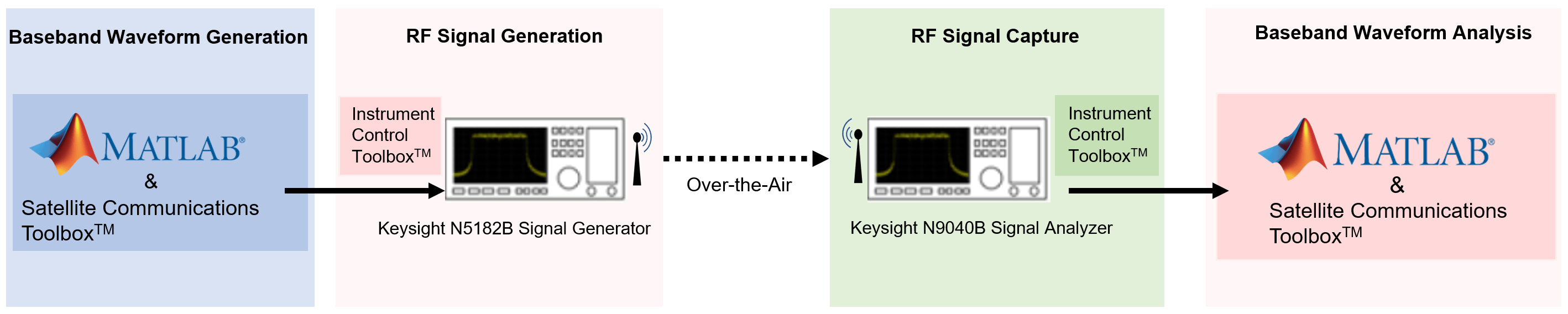
This example shows how to generate Digital Video Broadcasting Satellite Second Generation (DVB-S2) physical layer (PL) frames using the Wireless Waveform Generator App and download the generated waveform to a Keysight™ vector signal generator for over-the-air transmission using the Instrument Control Toolbox™ software. The example then captures the transmitted over-the-air signal using a Keysight signal analyzer, decodes the PL frames and analyzes the signal in MATLAB®.
Introduction
This example generates a DVB-S2 baseband waveform using the Wireless Waveform Generator app, downloads the waveform onto a Keysight vector signal generator, and transmits it over the air using the Instrument Control Toolbox. A Keysight signal analyzer then captures the data corrupted by over-the-air transmission at a sample rate of 4 Msps, after which baseband waveform analysis is performed.
Requirements
To run this example, you need:
Instrument Control Toolbox
Satellite Communications Toolbox
Communications Toolbox
Instrument Control Toolbox Support Package for Keysight (Agilent) IO Libraries and VISA Interface
Keysight N5182B vector signal generator
Keysight N9040B UXA signal analyzer
The Keysight vector signal generator device in this setup transmits DVB-S2 in-phase and quadrature phase (IQ) samples at the specified frequency and symbol rate.
This diagram summarizes the transmission, capture, and the general workflow.
Download DVB-S2 LDPC Parity Matrices Data Set
Load a MAT file containing DVB-S2 LDPC parity matrices.These are a set of matrices used in the DVB-S2 standard for error correction, and are used to encode and decode data to ensure reliable transmission over satellite.
If the MAT file is not available on the MATLAB path, use these commands to download and unzip the MAT file.
if ~exist('dvbs2xLDPCParityMatrices.mat','file')
    if ~exist('s2xLDPCParityMatrices.zip','file')
        url = 'https://ssd.mathworks.com/supportfiles/spc/satcom/DVB/s2xLDPCParityMatrices.zip';
        websave('s2xLDPCParityMatrices.zip',url);
        unzip('s2xLDPCParityMatrices.zip');
    end
    addpath('s2xLDPCParityMatrices');
end
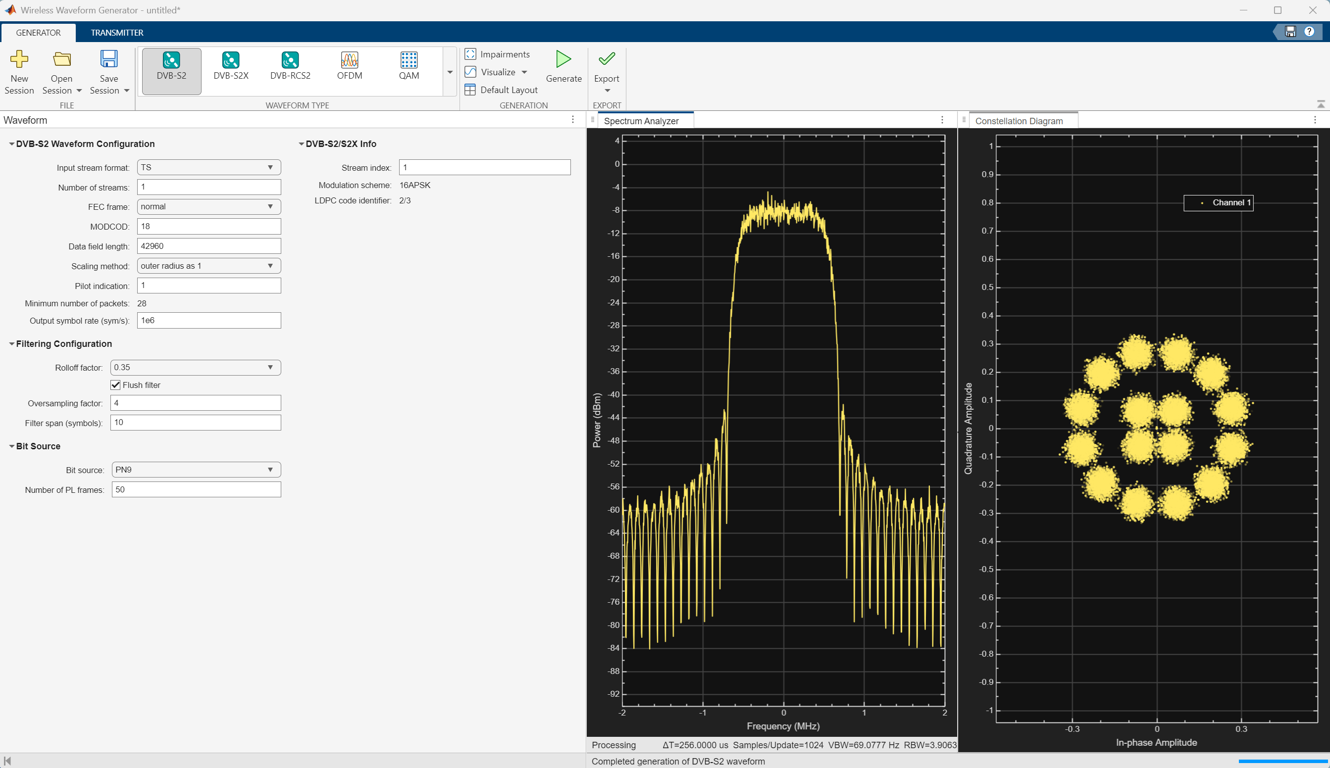
Generate Baseband Waveform Using Wireless Waveform Generator App
In MATLAB, on the Apps tab, click the Wireless Waveform Generator app.
In the Waveform Type section, click DVB-S2. Digital Video Broadcasting Satellite Second Generation (DVB-S2) is a physical layer standard to support high-data-rate satellite communications in space.
In the left-most pane of the app, you can set the parameters for the selected waveform. For this example:
Under DVB-S2 Waveform Configuration:
Set Input stream format as
TSSet Number of streams as 1
Set FEC Frame as normal
Set MODCOD as 18
Set Data field length as 42960
Set Pilot Indication as 1
Set Output symbol rate (sym/s) as 1e6
Under Filtering Configuration:
Set Rolloff factor as 0.35
Set Oversampling factor as 4
Set Filter span (symbols) as 10
Under Bit Source:
Set Bit Source as PN9
Set Number of PL frames as 50
On the app toolstrip, click Generate.
This figure shows a DVBS2 waveform visible at baseband.
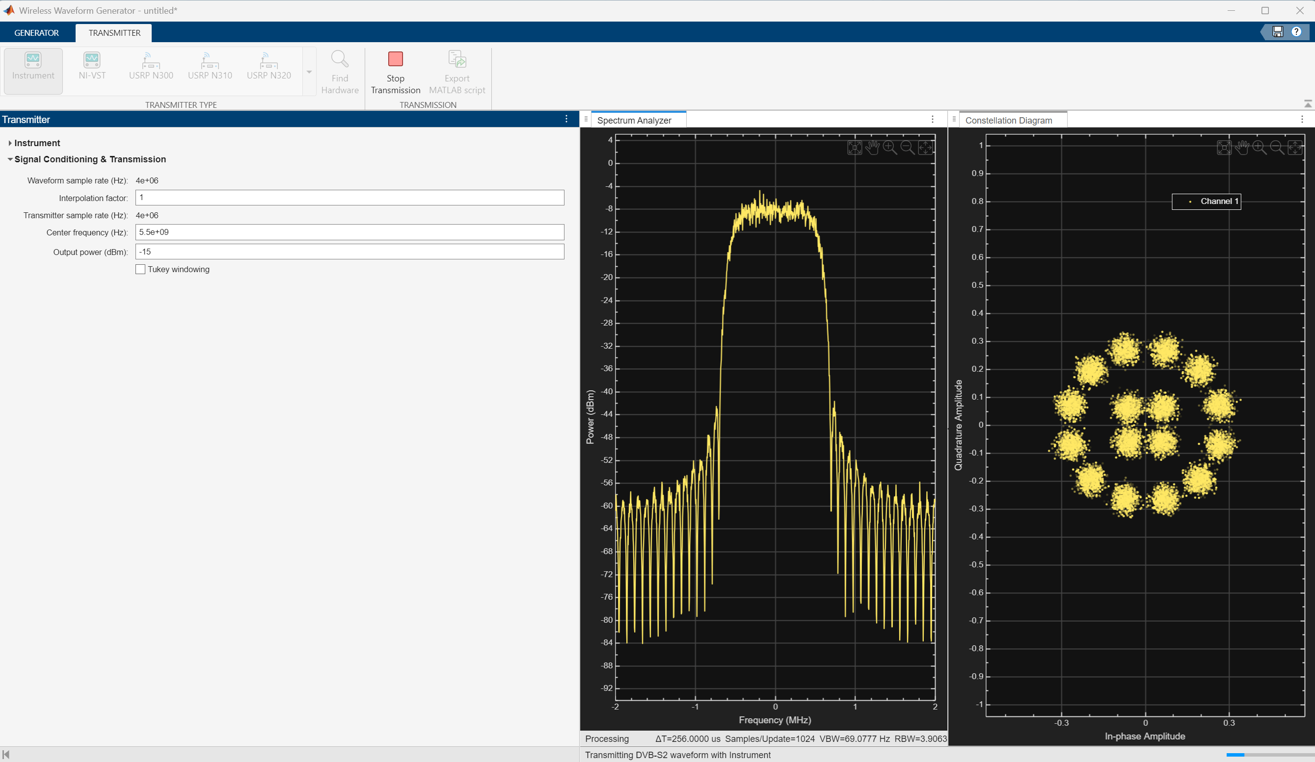
Transmit Baseband Waveform Over-the-Air Using Wireless Waveform Generator App
Download the generated signal to the RF signal generator over one of the supported communication interfaces (requires Instrument Control Toolbox). The app automatically finds the signal generator that is connected over the TCP/IP interface. On the Transmitter tab of the app, select Agilent/Keysight Signal Generator SCPI from the Driver list. Set the Center frequency (Hz) parameter to 5.5e9 and the Output power (dBm) parameter to -15. The app automatically obtains the baseband sample rate from the generated waveform. To start the transmission, click Transmit in the toolstrip.
Read IQ Data from a Signal Analyzer over TCP/IP
To read the in-phase and quadrature (IQ) data into MATLAB for analysis, configure the Keysight N9040B signal analyzer using the Instrument Control Toolbox software.
Define the instrument configuration parameters based on the signal you are measuring.
% Set parameters for the spectrum analyzer
centerFrequency = 5.5e9;
measurementTime = 800e-3;
mechanicalAttenuation = 0;
startFrequency = 5.49e9;
stopFrequency = 5.51e9;
resolutionBandwidth = 220e3;
videoBandwidth = 220e3;
Initialize Receiver Parameters
At the receiver, you first perform DC offset compensation, followed by automatic gain control (AGC), symbol timing synchronization, and then frame synchronization, in order. The receiver algorithms include coarse and fine frequency impairment correction algorithms. The preferred loop bandwidth for symbol timing and coarse frequency compensation depends on the setting. If the captured signal is buried under noise, you can reduce the loop bandwidth to filter out more noise during acquisition. The number of frames required for the symbol synchronization and frame synchronization depends on the loop bandwidth setting.
Set the rxParams fields structure for synchronization processing. Set valid values for fecFrame, modCod, Fsamp, and Rsym, for proper capture and validation of the demodulated signal.
fecFrame = "normal";                            % DVB-S2 FECFrame type
modCod = 18;                                    % 32APSK 3/4
Fsamp = 4e6;                                    % Sampling rate in samples per second
Rsym = 1e6;                                     % Symbol rate in symbols per second
sps = Fsamp/Rsym;
numFrames = 50;
rxParams = getRxParams(fecFrame,modCod);
rxParams.carrSyncLoopBW            = 1e-4;      % Coarse frequency estimator loop bandwidth normalized by symbol rate
rxParams.symbSyncLoopBW            = 1e-4;      % Symbol timing synchronizer loop bandwidth normalized by symbol rate
rxParams.symbSyncLock              = 2;         % Number of frames required for symbol timing error convergence
rxParams.frameSyncLock             = 1;         % Number of frames required for frame synchronization
rxParams.sps = sps;
% Total frames taken for symbol timing and frame synchronization to happen
rxParams.initialTimeSync = rxParams.symbSyncLock + rxParams.frameSyncLock;
rxParams.initialTimeFreqSync = numFrames;
rxParams.totalSyncFrames = numFrames;
Capture DVB-S2 Waveform Using Signal Analyzer Instrument
Perform these steps to connect to the signal analyzer. instrument:
Find the resource ID of the Keysight N9040B signal analyzer.
Connect to the instrument using the visadev interface.
Set the ByteOrder on the signal analyzer to match the ByteOrder used by the transmitter.
Set the timeout to allow sufficient time for the measurement and data transfer.
foundVISA = visadevlist;
resourceID = foundVISA(foundVISA.Model == "N9040B",:).ResourceName;
sigAnalyzerObj = visadev(resourceID);
sigAnalyzerObj.ByteOrder = "big-endian";
sigAnalyzerObj.Timeout = 20;
Reset the instrument to a known state by sending the appropriate SCPI command. Query the instrument identity to ensure the correct instrument is connected.
writeline(sigAnalyzerObj,"*RST");
instrumentInfo = writeread(sigAnalyzerObj,"*IDN?");
fprintf("Instrument identification information: %s",instrumentInfo);
Instrument identification information: Keysight Technologies,N9040B,US00091124,A.36.00_D0071
The X-Series signal and spectrum analyzers perform IQ measurements as well as spectrum measurements. In this example, you acquire time domain IQ data, visualize the data using MATLAB, and perform signal analysis on the acquired data. The SCPI commands configure the instrument and define the format of the data transfer after the measurement is complete.
% Set up signal analyzer mode to basic IQ mode
writeline(sigAnalyzerObj,":INSTrument:SELect BASIC");

% Set the center frequency
writeline(sigAnalyzerObj,strcat(":SENSe:FREQuency:CENTer ",num2str(centerFrequency)));

% Set the capture sample rate
writeline(sigAnalyzerObj,strcat(":SENSe:WAVeform:SRATe ",num2str(Fsamp)));

% Turn off averaging
writeline(sigAnalyzerObj,":SENSe:WAVeform:AVER OFF");

% Set the spectrum analyzer to take one single measurement after the trigger line goes high
writeline(sigAnalyzerObj,":INIT:CONT OFF");

% Set the trigger to external source 1 with positive slope triggering
writeline(sigAnalyzerObj,":TRIGger:WAVeform:SOURce IMMediate");
writeline(sigAnalyzerObj,":TRIGger:LINE:SLOPe POSitive");

% Set the time for which measurement needs to be made
writeline(sigAnalyzerObj,strcat(":WAVeform:SWE:TIME ",num2str(measurementTime)));

% Turn off electrical attenuation
writeline(sigAnalyzerObj,":SENSe:POWer:RF:EATTenuation:STATe OFF");

% Set the mechanical attenuation level
writeline(sigAnalyzerObj,strcat(":SENSe:POWer:RF:ATTenuation ",num2str(mechanicalAttenuation)));

% Turn IQ signal ranging to auto
writeline(sigAnalyzerObj,":SENSe:VOLTage:IQ:RANGe:AUTO ON");

% Set the endianness of returned data
writeline(sigAnalyzerObj,":FORMat:BORDer NORMal");

% Set the format of the returned data
writeline(sigAnalyzerObj,":FORMat:DATA REAL,64");
Trigger the instrument to make the measurement. Wait for the measurement operation to complete, and then read-in the waveform. Before processing the data, separate the I and Q components from the interleaved data that is received from the instrument and create a complex vector in MATLAB.
writeline(sigAnalyzerObj,"*TRG");
writeline(sigAnalyzerObj,":INITiate:WAVeform");
measureComplete = writeread(sigAnalyzerObj,"*OPC?");
writeline(sigAnalyzerObj,":READ:WAV0?");
data = readbinblock(sigAnalyzerObj,"double");

% Create the IQ vector
inphase = data(1:2:end);
quadrature = data(2:2:end);
rxWaveform = inphase+1i*quadrature;
Capture and display the information about the most recently acquired data.
writeline(sigAnalyzerObj,":FETCH:WAV1?");
signalSpec = readbinblock(sigAnalyzerObj,"double");
captureSampleRate = 1/signalSpec(1);
fprintf("Sample Rate (Hz) = %s",num2str(captureSampleRate));
Sample Rate (Hz) = 4000000
fprintf("Number of points read = %s",num2str(signalSpec(4)));Number of points read = 3200001
fprintf("Max value of signal (dBm) = %s",num2str(signalSpec(6)));Max value of signal (dBm) = -10.5522
fprintf("Min value of signal (dBm) = %s",num2str(signalSpec(7)));Min value of signal (dBm) = -94.96
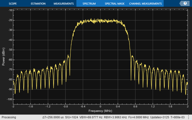
Visualize Received Waveform
Visualize the spectrum of the captured waveform. Transform rxwaveform into a column vector for the spectrumAnalyzer object.
rxWaveform = rxWaveform.';
specAn = spectrumAnalyzer(SampleRate=Fsamp);
specAn(rxWaveform)
Initialize Receiver Processing System Objects
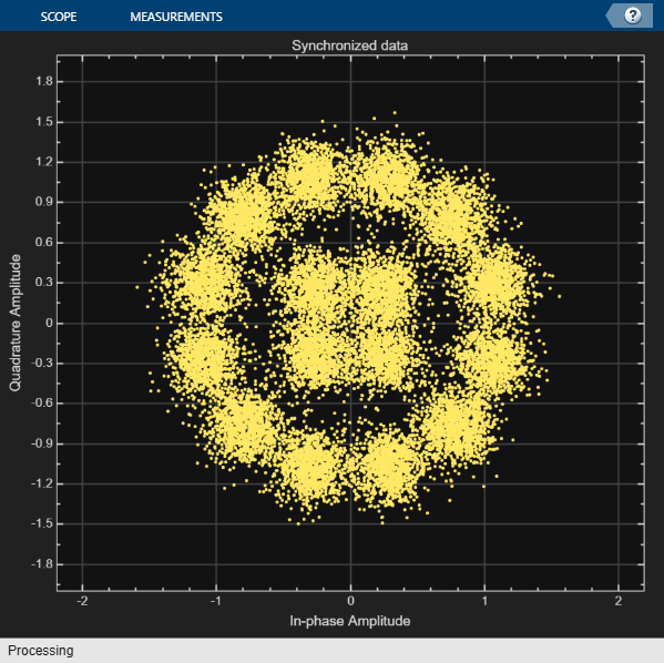
After examining the received signal spectrum, proceed to initialize the receiver processing System objects required for synchronization and signal conditioning. Create a time and coarse frequency synchronization System object™ by using the HelperDVBS2TimeFreqSynchronizer helper object. Initialize the comm.AGC, dsp.DCBlocker, and comm.ConstellationDiagram System objects.
timeFreqSync = HelperDVBS2TimeFreqSynchronizer( ...
    CarrSyncLoopBW=rxParams.carrSyncLoopBW, ...
    SymbSyncLoopBW=rxParams.symbSyncLoopBW, ...
    SamplesPerSymbol=rxParams.sps, ...
    DataFrameSize=rxParams.xFecFrameSize, ...
    SymbSyncTransitFrames=rxParams.symbSyncLock, ...
    FrameSyncAveragingFrames=rxParams.frameSyncLock);

agc = comm.AGC(AveragingLength=2000,AdaptationStepSize = 0.001);

dcBlock = dsp.DCBlocker(Algorithm="FIR",Length=100);

syncConst = comm.ConstellationDiagram(Title="Synchronized data", ...
XLimits=[-2 2], ...
YLimits=[-2 2], ...
ShowReferenceConstellation = false);
[numFramesLost,pktsErr,bitsErr,pktsRec,stIdx,numFreqEst] = deal(0);

% Initialize data indexing variables
plFrameSize = rxParams.plFrameSize;
symSyncOutLen = zeros(rxParams.initialTimeFreqSync,1);
freqCounter = 0;
isCoarseFreqLock = false;
cCFOEstMean = [];
isFineFreqLock = false;
cCFOEst = [];
rxParams.fineFreqEstTemp = zeros(numFrames-rxParams.initialTimeSync,1);
headerDataDisplayCounter = 0;
streamFormat = "packetized";
Synchronization and Data Recovery
To synchronize the received data and recover the input bit stream, process the distorted DVB-S2 waveform samples one frame at a time by following these steps.
Apply DC offset compensation to remove any DC components.
Apply AGC to normalize the input signal amplitude.
Apply matched filtering, outputting at a rate of 2 samples per symbol.
Apply symbol timing synchronization using the Gardner timing error detector (TED) with an output generated at the symbol rate. The Gardner TED is not data-aided, so you can perform before carrier synchronization.
Apply frame synchronization to detect the start of frame and to identify the pilot positions.
Estimate and apply coarse frequency offset correction.
Estimate and apply fine frequency offset correction.
Estimate and compensate for residual carrier frequency and phase noise.
Decode the PL header and compute the transmission parameters.
Demodulate and decode the PL frames.
Perform CRC check on the BB header. If the check passes, recover the header parameters.
Regenerate the input stream of data or packets from BB frames.
while stIdx < length(rxWaveform)

    % Use one DVB-S2 PL frame for each iteration.
    endIdx = stIdx + rxParams.plFrameSize*rxParams.sps;

    % In the last iteration, consider all the remaining samples in the received
    % waveform.
    isLastFrame = endIdx > length(rxWaveform);
    endIdx(isLastFrame) = length(rxWaveform);
    rxData = rxWaveform(stIdx+1:endIdx);

    % After coarse frequency offset loop is converged, the FLL works with a
    % reduced loop bandwidth.
    if rxParams.frameCount < rxParams.initialTimeFreqSync
        isCoarseFreqLock = false;
    else
        isCoarseFreqLock = true;
    end

    % Retrieve the last frame samples.
    if isLastFrame
        resSymb = plFrameSize - length(rxParams.cfBuffer);
        resSampCnt = resSymb*rxParams.sps - length(rxData);
        if resSampCnt >= 0                                    % Inadequate number of samples to fill last frame
            syncIn = [rxData;zeros(resSampCnt,1)];
        else                                                  % Excess samples are available to fill last frame
            syncIn = rxData(1:resSymb*rxParams.sps);
        end
    else
        syncIn = rxData;
    end

    % Apply DC offset compensation, AGC, matched filtering, symbol timing synchronization, frame
    % synchronization, and coarse frequency offset compensation.
    syncIn = dcBlock(syncIn);
    syncIn = agc(syncIn)/sps;
    if rxParams.frameCount > 1
        [coarseFreqSyncOut,syncIndex,phEst] = timeFreqSync(syncIn,isCoarseFreqLock);
        coarseCFOEst = diff(phEst(1:sps:end)/(2*pi));
        if rxParams.frameCount <= rxParams.initialTimeSync
            symSyncOutLen = [symSyncOutLen;length(coarseFreqSyncOut)]; %#ok<*AGROW>
            if any(abs(diff(symSyncOutLen(1:rxParams.frameCount))) > 5)
                error(["Symbol timing synchronization failed. The loop will not " ...
                    "converge, resulting in frame recovery. Decrease the symbSyncLoopBW " ...
                    "parameter for proper loop convergence."]);
            end
        end
        if rxParams.frameCount > rxParams.initialTimeSync + 1
            cCFOEstMean = [cCFOEstMean;mean(coarseCFOEst)];
            cCFOEst = [cCFOEst;coarseCFOEst];
            if length(cCFOEstMean) > 2
                diffVal = diff(abs(cCFOEstMean));
                if all(diffVal(end-1:end) < 0.01) && ~isCoarseFreqLock
                    isCoarseFreqLock = true;
                    rxParams.initialTimeFreqSync = rxParams.frameCount;
                elseif isLastFrame && ~isCoarseFreqLock
                    fprintf("%s\n",["Coarse frequency error estimation failed. Try analyzing the cCFOEst " ...
                        "across frames and check carrier synchronization has converged. Try reducing the " ...
                        "carrSyncLoopBW parameters"]);
                end
            end
        end
        rxParams.syncIndex = syncIndex;
        % The PL frame start index lies somewhere in the middle of the frame being processed.
        % From fine frequency estimation, the processing happens as a PL frame.
        % A buffer stores the symbols required to fill one PL frame.
        if isLastFrame
            fineFreqIn = [rxParams.cfBuffer; coarseFreqSyncOut];
        elseif rxParams.frameCount > 1
            buffLen = rxParams.plFrameSize - length(rxParams.cfBuffer);
            if buffLen < length(coarseFreqSyncOut)
                fineFreqIn = [rxParams.cfBuffer; coarseFreqSyncOut(1:buffLen)];
            else
                fineFreqIn = [rxParams.cfBuffer; coarseFreqSyncOut];
            end
        end
        % Estimate the fine frequency error by using the HelperDVBS2FineFreqEst
        % helper function.
        % Add 1 to the conditional check because the buffer used to get one PL
        % frame introduces a delay of one to the loop count.
        if (rxParams.frameCount > rxParams.initialTimeFreqSync + 1) && ...
                ~isFineFreqLock
            rxParams.fineFreqCorrVal = HelperDVBS2FineFreqEst( ...
                fineFreqIn(rxParams.pilotInd),rxParams.numPilots, ...
                rxParams.refPilots,rxParams.fineFreqCorrVal);
            % Normalize the frequency estimate by the input symbol rate
            % freqEst = angle(R)/(pi*(N+1)), where N (18) is the number of elements
            % used to compute the mean of auto correlation (R) in
            % HelperDVBS2FineFreqEst.
            freqEst = angle(rxParams.fineFreqCorrVal)/(pi*(19));
            rxParams.fineFreqEstTemp(1:end-1) = rxParams.fineFreqEstTemp(2:end);
            rxParams.fineFreqEstTemp(end) = freqEst;
            numFreqEst = numFreqEst + 1;
            if numFreqEst >= 5
                cg = abs(diff(rxParams.fineFreqEstTemp));
                if all(cg(end-2:end) < 1e-4)
                    isFineFreqLock = true;
                    rxParams.totalSyncFrames = rxParams.frameCount;
fprintf("Estimated carrier frequency offset in Hz = %f\n",(coarseCFOEst(end) + freqEst).*Rsym);
                elseif isLastFrame && ~isFineFreqLock
                    fprintf("%s\n","Fine frequency error estimation failed. Try analyzing the pilot fields in the PL frame to debug the issue.")
                end
            end
        end
        if isFineFreqLock
            % Normalize the frequency estimate by the input symbol rate
            % freqEst = angle(R)/(pi*(N+1)), where N (18) is the number of elements
            % used to compute the mean of auto correlation (R) in
            % HelperDVBS2FineFreqEst.
            freqEst = angle(rxParams.fineFreqCorrVal)/(pi*(19));

            % Generate the symbol indices using frameCount and plFrameSize.
            % Subtract 2 from the rxParams.frameCount because the buffer used to get one
            % PL frame introduces a delay of one to the count.
            ind = (rxParams.frameCount-2)*plFrameSize:(rxParams.frameCount-1)*plFrameSize-1;
            phErr = exp(-1j*2*pi*freqEst*ind);
            fineFreqOut = fineFreqIn.*phErr(:);

            % Estimate the phase error estimation by using the HelperDVBS2PhaseEst
            % helper function.
            [phEstRes,rxParams.prevPhaseEst] = HelperDVBS2PhaseEst( ...
                fineFreqOut,rxParams.refPilots,rxParams.prevPhaseEst,rxParams.pilotInd);

            % Compensate for the residual frequency and phase offset by using
            % the HelperDVBS2PhaseCompensate helper function.
            if rxParams.frameCount >= rxParams.totalSyncFrames + 2
                phaseCompOut = HelperDVBS2PhaseCompensate(rxParams.ffBuffer, ...
                    rxParams.pilotEst,rxParams.pilotInd,phEstRes(2));
            end

            rxParams.ffBuffer = fineFreqOut;
            rxParams.pilotEst = phEstRes;

            % Perform phase compensation on the data portion by
            % interpolating the phase estimates computed on consecutive pilot
            % blocks. The second phase estimate is not available for the data
            % portion after the last pilot block in the last frame. Therefore,
            % the slope of phase estimates computed on all pilot blocks in the
            % last frame is extrapolated and used to compensate for the phase
            % error on the final data portion.
            if isLastFrame
                pilotBlkLen = 36;                                               % Symbols
                pilotBlkFreq = 1476;                                            % Symbols
                avgSlope = mean(diff(phEstRes(2:end)));
                chunkLen = rxParams.plFrameSize - rxParams.pilotInd(end) + ...
                    rxParams.pilotInd(pilotBlkLen);
                estEndPh = phEstRes(end) + avgSlope*chunkLen/pilotBlkFreq;
                phaseCompOut1 = HelperDVBS2PhaseCompensate(rxParams.ffBuffer, ...
                    rxParams.pilotEst,rxParams.pilotInd,estEndPh);
            end
        end

        % Recover the input bit stream.
        if rxParams.frameCount >= rxParams.totalSyncFrames + 2
            isValid = true;
            if isLastFrame
                syncOut = [phaseCompOut; phaseCompOut1];
            else
                syncOut = phaseCompOut;
            end
        else
            isValid = false;
            syncOut = [];
        end

        % Update the buffers and counters.
        rxParams.cfBuffer = coarseFreqSyncOut(rxParams.syncIndex:end);

        if isValid  % Data valid signal

            % Decode the PL header by using the dvbsPLHeaderRecover
            % function
            syncOut = syncOut/sqrt(mean(abs(syncOut).^2));
            rxPLHeader = syncOut(1:90);
            phyParams = dvbsPLHeaderRecover(rxPLHeader,Mode="DVB-S2/S2X regular");
            M = phyParams.ModulationOrder;
            R = eval(phyParams.LDPCCodeIdentifier);
            fecFrame = phyParams.FECFrameLength;
            pilotStat = phyParams.HasPilots;
            xFECFrameLen = fecFrame/log2(M);
            % Validate the decoded PL header.
            if M ~= rxParams.modOrder || abs(R-rxParams.codeRate) > 1e-3 || ...
                    fecFrame ~= rxParams.cwLen || ~pilotStat
                fprintf("Pl frame number %d , %s\n",rxParams.frameCount, ...
                    "PL header decoding failed")
            else                                                                % Demodulation and decoding
                if ~headerDataDisplayCounter
fprintf("%s\n","Physical layer header detection summary")
detPLParams = generatePLParamsTable(M,R,fecFrame,pilotStat)
                    headerDataDisplayCounter = headerDataDisplayCounter + 1;
                end
                rxFrame = syncOut(1:plFrameSize);
                % Synchronized data constellation plot
syncConst(rxFrame)
                % Estimate noise variance by using
                % HelperDVBS2NoiseVarEstimate helper function.
                nVar = HelperDVBS2NoiseVarEstimate(rxFrame,rxParams.pilotInd,...
                    rxParams.refPilots,false);
                snr_dB = 10*log10(1/nVar);
fprintf("PL frame number = %d\n",rxParams.frameCount)
fprintf("Estimated SNR in dB = %f\n",snr_dB)
                % Recover the input bit stream by using
                % dvbs2BitRecover function
                [decBitsTemp,isFrameLost,pktCRC]  = dvbs2BitRecover(rxFrame,nVar);
                decBits = decBitsTemp{:};
                if ~isLastFrame
                    pktsErr = pktsErr + numel(pktCRC{:}) - sum(pktCRC{:});
                    pktsRec = pktsRec + numel(pktCRC{:});
                end
                if ~isFrameLost
fprintf("%s\n","BB header decoding passed")
                    if isempty(pktCRC{1})
                        streamFormat = "continuous";
                    else
                        streamFormat = "packetized";
                    end
                else
                    fprintf("%s\n","BB header decoding failed")
                end
                % Compute the number of frames lost. Consider CRC failure of the baseband header
                % as a frame loss.
                numFramesLost = isFrameLost + numFramesLost;
fprintf("Total number of frames lost = %1d\n",numFramesLost)
            end

        end
    end
    stIdx = endIdx;
    rxParams.frameCount = rxParams.frameCount + 1;
end
Estimated carrier frequency offset in Hz = 1772.097899
Physical layer header detection summary
detPLParams=1×4 table
    "16APSK"    "2/3"    "normal"    "true"
PL frame number = 15
Estimated SNR in dB = 12.905461
BB header decoding passed
Total number of frames lost = 0
PL frame number = 16
Estimated SNR in dB = 13.008344
BB header decoding passed
Total number of frames lost = 0
PL frame number = 17
Estimated SNR in dB = 12.509743
BB header decoding passed
Total number of frames lost = 0
PL frame number = 18
Estimated SNR in dB = 12.698449
BB header decoding passed
Total number of frames lost = 0
PL frame number = 19
Estimated SNR in dB = 12.478942
BB header decoding passed
Total number of frames lost = 0
PL frame number = 20
Estimated SNR in dB = 12.467469
BB header decoding passed
Total number of frames lost = 0
PL frame number = 21
Estimated SNR in dB = 12.203213
BB header decoding passed
Total number of frames lost = 0
PL frame number = 22
Estimated SNR in dB = 12.799633
BB header decoding passed
Total number of frames lost = 0
PL frame number = 23
Estimated SNR in dB = 12.367894
BB header decoding passed
Total number of frames lost = 0
PL frame number = 24
Estimated SNR in dB = 12.763959
BB header decoding passed
Total number of frames lost = 0
PL frame number = 25
Estimated SNR in dB = 12.355102
BB header decoding passed
Total number of frames lost = 0
PL frame number = 26
Estimated SNR in dB = 13.135598
BB header decoding passed
Total number of frames lost = 0
PL frame number = 27
Estimated SNR in dB = 12.723067
BB header decoding passed
Total number of frames lost = 0
PL frame number = 28
Estimated SNR in dB = 13.030082
BB header decoding passed
Total number of frames lost = 0
PL frame number = 29
Estimated SNR in dB = 12.416891
BB header decoding passed
Total number of frames lost = 0
PL frame number = 30
Estimated SNR in dB = 13.409706
BB header decoding passed
Total number of frames lost = 0
PL frame number = 31
Estimated SNR in dB = 12.746534
BB header decoding passed
Total number of frames lost = 0
PL frame number = 32
Estimated SNR in dB = 12.179928
BB header decoding passed
Total number of frames lost = 0
PL frame number = 33
Estimated SNR in dB = 13.038020
BB header decoding passed
Total number of frames lost = 0
PL frame number = 34
Estimated SNR in dB = 12.640759
BB header decoding passed
Total number of frames lost = 0
PL frame number = 35
Estimated SNR in dB = 13.542063
BB header decoding passed
Total number of frames lost = 0
PL frame number = 36
Estimated SNR in dB = 12.794870
BB header decoding passed
Total number of frames lost = 0
PL frame number = 37
Estimated SNR in dB = 13.091238
BB header decoding passed
Total number of frames lost = 0
PL frame number = 38
Estimated SNR in dB = 12.852279
BB header decoding passed
Total number of frames lost = 0
PL frame number = 39
Estimated SNR in dB = 12.838353
BB header decoding passed
Total number of frames lost = 0
PL frame number = 40
Estimated SNR in dB = 13.100813
BB header decoding passed
Total number of frames lost = 0
PL frame number = 41
Estimated SNR in dB = 12.727261
BB header decoding passed
Total number of frames lost = 0
PL frame number = 42
Estimated SNR in dB = 13.153455
BB header decoding passed
Total number of frames lost = 0
PL frame number = 43
Estimated SNR in dB = 13.457814
BB header decoding passed
Total number of frames lost = 0
PL frame number = 44
Estimated SNR in dB = 13.545653
BB header decoding passed
Total number of frames lost = 0
PL frame number = 45
Estimated SNR in dB = 12.983854
BB header decoding passed
Total number of frames lost = 0
PL frame number = 46
Estimated SNR in dB = 12.866556
BB header decoding passed
Total number of frames lost = 0
PL frame number = 47
Estimated SNR in dB = 12.834604
BB header decoding passed
Total number of frames lost = 0
PL frame number = 48
Estimated SNR in dB = 12.783392
BB header decoding passed
Total number of frames lost = 0
Visualization and Error Logs
Plot the constellation of the synchronized data and compute PER.
% Error metrics display
% For GS and TS packetized streams
if strcmp(streamFormat,"packetized")
    if pktsRec == 0
        fprintf("All frames are lost. No packets are retrieved from BB frames.")
    else
        per = pktsErr/pktsRec;
fprintf("PER: %1.2e\n",per)
    end
end
PER: 0.00e+00
Instrument Connection Troubleshooting
Try the troubleshooting tips mentioned on the Troubleshooting VISA Interface page.
Further Exploration
5G NR Waveform Acquisition and Analysis (5G Toolbox) example - Generate a 5G NR-TM waveform using the 5G Waveform Generator app, download and transmit the waveform onto a Keysight vector signal generator, and then receive the waveform using a Keysight signal analyzer for waveform analysis in MATLAB.
For details on how to configure the synchronization parameters of the
rxParamsfor other configurations, see the Further Exploration section of the example DVB-S2 Link Simulation with RF Impairments and Corrections (Satellite Communications Toolbox™).
Supporting Files
The example uses these helper functions and data file:
HelperDVBS2TimeFreqSynchronizer.m: Perform matched filtering, symbol timing synchronization, frame synchronization, and coarse frequency estimation and correctionHelperDVBS2FrameSync.m: Perform frame synchronization and detect the start of frameHelperDVBS2FineFreqEst.m: Estimate fine frequency offsetHelperDVBS2PhaseEst.m: Estimate carrier phase offsetHelperDVBS2PhaseCompensate.m: Perform carrier phase compensationHelperDVBS2NoiseVarEstimate.m: Estimate noise variance of received data
References
ETSI Standard EN 302 307-1 V1.4.1(2014-11). Digital Video Broadcasting (DVB); Second Generation Framing Structure, Channel Coding and Modulation Systems for Broadcasting, Interactive Services, News Gathering and other Broadband Satellite Applications (DVB-S2).
ETSI Standard TR 102 376-1 V1.2.1(2015-11). Digital Video Broadcasting (DVB); Implementation Guidelines for the Second Generation System for Broadcasting, Interactive Services, News Gathering and other Broadband Satellite Applications (DVB-S2).
Local Functions
function rxParams = getRxParams(fecFrame,modCod)
% Receiver parameters generation

[modOrder,codeRate,cwLen] = satcom.internal.dvbs.getS2PHYParams(modCod,fecFrame);

dataLen = cwLen/log2(modOrder);

% Pilot sequence and indices generation
slotLen = 90;
pilotBlkFreq = 16;                                                    % In slots
numPilotBlks = floor(dataLen/(slotLen*pilotBlkFreq));
if floor(dataLen/(slotLen*16)) == dataLen/(slotLen*pilotBlkFreq)
    numPilotBlks = numPilotBlks - 1;
end
pilotLen = numPilotBlks*36;                                           % One pilot block contains 36 pilot symbols
frameSize = dataLen + pilotLen + slotLen;
plScrambIntSeq = satcom.internal.dvbs.plScramblingIntegerSequence(0);
cMap = [1 1j -1 -1j].';
cSeq = cMap(plScrambIntSeq+1);
[~, pilotInd] = satcom.internal.dvbs.pilotBlock(numPilotBlks);

rxParams.plFrameSize = frameSize;
rxParams.xFecFrameSize = dataLen;
rxParams.modOrder = modOrder;
rxParams.codeRate = codeRate;
rxParams.cwLen = cwLen;
rxParams.frameCount = 1;
rxParams.numPilots = numPilotBlks;
rxParams.pilotInd = pilotInd + slotLen;
rxParams.refPilots = (1+1j)/sqrt(2).*cSeq(pilotInd);
rxParams.cfBuffer = [];
rxParams.ffBuffer = complex(zeros(frameSize, 1));
rxParams.pilotPhEst = zeros(numPilotBlks+1, 1);
[rxParams.prevPhaseEst, rxParams.fineFreqCorrVal] = deal(0);
rxParams.syncIndex = 1;
end
function tbl =  generatePLParamsTable(M,R,fecFrame,pilotStat)
modScheme = ["QPSK" "8PSK" "16APSK" "32APSK"];
Modulation = modScheme(log2(M)-1);
[n,d] = rat(R);
CodeRate = strcat(string(n),"/",string(d));
if fecFrame == 64800
    FECFrame = "normal";
else
    FECFrame = "short";
end
if pilotStat
    PilotStatus = "true";
else
    PilotStatus = "false";
end
tbl = table(Modulation,CodeRate,FECFrame,PilotStatus);
tbl = renamevars(tbl,["Modulation","CodeRate","FECFrame", "PilotStatus"],["Modulation","Code Rate","FEC Frame", "Pilot Status"]);
end