Getting Started with Radar Signal Generation Using NI-RFSG Scripting
This example shows how to generate a realistic radar pulse train using an NI™ VST. Specifically, it demonstrates how to generate a pulse train comprising 100 MHz wide chirps, initially using a simple functional definition, and finally using scripting and waveform sequences.
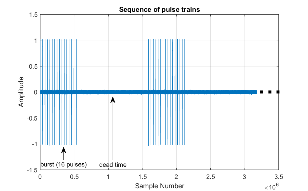
Set Up
Clear the current workspace and set the output display format to short engineering notation.
clear;
format shortEng;
Define Radar Pulse Train Parameters
Specify the radar pulse train parameters for center frequency, sweep bandwidth, sampling frequency, PRI, PRF, and the idle time.
Note that oversampling is used to improve visualization but is not otherwise necessary.
fc              = 2.8e9;            % Radar center frequency
sweepBandwidth  = 100e6;
fs              = 8*sweepBandwidth; % Oversample to ensure a smooth time-domain visualization
pulseWidth      = 10e-6;
PRI             = 16*pulseWidth;    % Pulse repetition interval
PRF             = 1/PRI;            % Pulse repetition frequency
pulsesPerTrain  = 8;
idleTime        = 2e-3;
Define Radar Pulse Train
Define a full radar pulse train with the specified parameters.
waveformGenerator = phased.LinearFMWaveform(... SampleRate=fs, ... PulseWidth=pulseWidth, ... PRF=1/PRI, ... SweepBandwidth=sweepBandwidth, ... SweepInterval="Positive", ... SweepDirection=
"Up", ... OutputFormat="Pulses", ... NumPulses=pulsesPerTrain, ... Envelope="Rectangular");
Create pulse train and dead time samples separately.
pulses = waveformGenerator();
idleSamples = zeros(ceil(idleTime*fs), 1, 'like', pulses);

pulseTrain = [pulses; idleSamples];
lenTrain = length(pulseTrain);
Visualize the radar pulse train in the time-domain.
tdScope = timescope(SampleRate=fs, ...
                    TimeSpan=lenTrain/fs, ...
                    BufferLength=lenTrain);

tdScope(pulseTrain)
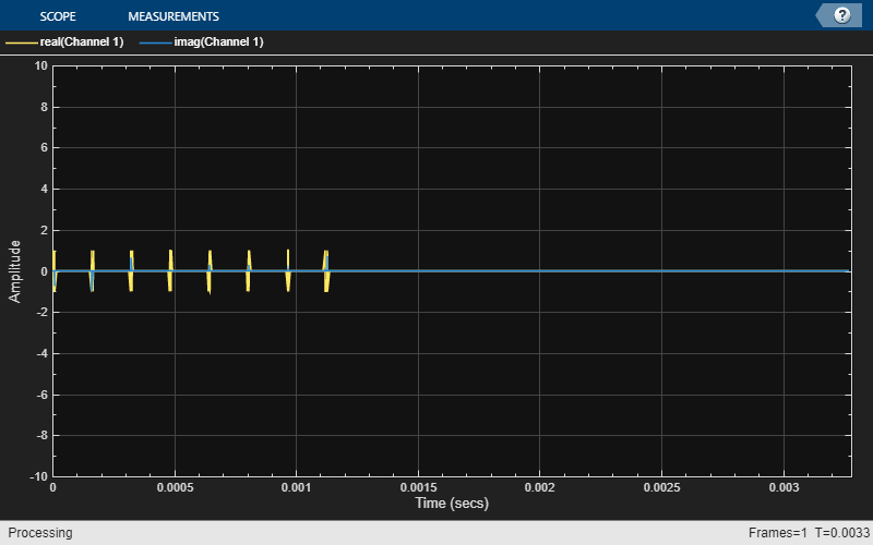
Visualize the spectrogram of the radar pulse train.
nfft = 8*1024;
nov = floor(nfft/2);
spectrogram(pulses,hamming(nfft),nov,nfft,fs,'centered','xaxis','MinThreshold',-110);
colormap ("bone")

Connect to Instrument
Connect to VST instrument using the ividev function. To determine or change the resource name for your system, use the NI Measurement and Automation Explorer (NI-MAX). For this example, specify the driver name as niRFSG, the resource name as PXI1Slot2, and the IVI driver setup name-value argument as Model:5841.
Alternatively, you can leave the resource name unspecified ("") for simulated hardware. The driver setup is also optional. If you do not specify a name-value argument for the driver setup, ividev uses default setup values. For more information about default argument values, see ividev.
isSimulated =false; deviceID = "PXI1Slot2"; if isSimulated vsg = ividev("niRFSG", deviceID, Simulate=true, DriverSetup="Model:5841"); else vsg = ividev("niRFSG", deviceID); end
Generate Pulse Trains Without Scripting
To generate pulse trains without scripting, you must copy all waveform samples to the VST's memory. For pulse trains, this is wasteful because most of the waveform consists of idle time.
Write Waveform to Instrument Memory
Configure the VST to generate an arbitrary waveform. Set the following parameters to the specified value.
Frequency to the radar center frequency
Reference power level to -10 dBm
Generation mode to arbitrary waveform
Set the prefilter gain to prevent overflow in the generator's internal filters
Signal bandwidth to match null-to-null bandwidth
peakPowerLevel_dBm = -10;
configureRF(vsg, fc, peakPowerLevel_dBm);

configureGenerationMode(vsg, "ARB_WAVEFORM");
configurePowerLevelType(vsg, "PEAK_POWER");
vsg.Arb.IQRate = fs;
vsg.Arb.PrefilterGain = -2.0;
vsg.Arb.SignalBandwidth = 2/pulseWidth;

moreDataPending = false;
% To write a waveform, set the VSG to the configuration state.
abort(vsg);
waveformName = "SinglePulseTrain";
writeArbWaveform(vsg, waveformName, length(pulseTrain), real(pulseTrain), imag(pulseTrain), moreDataPending);
Generate Signal Continuously
Start a continuous generation.
initiate(vsg);
configureOutputEnabled(vsg, true);
isDone = checkGenerationStatus(vsg);
In this example, stop signal generation after five seconds or if an error occurs. Check the signal generation status for errors every 100 ms.
count = 1;
duration_s = 5;

fprintf('Starting Generation\n')
Starting Generation
while ~isDone && count <= 10*duration_s
    isDone = checkGenerationStatus(vsg);
    pause(0.100)
    count = count+1;
    % display indicator every second
    if mod(count, 10) == 0
        fprintf(".")
    end
end
.....
fprintf('\nStopping Generation')Stopping Generation
Stop generation.
configureOutputEnabled(vsg, false);
abort(vsg)
Generate Simple Sequence Using Script
In this example, the waveform (as previously defined) fits in memory and does not change in response to external events. For this scenario, arbitrary generation mode may be sufficient.
However, for situations where it is necessary to produce a complex sequence of waveforms that are possibly based on external events, you can take advantage of patterns in the waveform signal (waveform segments) to enable complex signal generation in the instrument. The following example demonstrates how to use scripting to produce a simple sequence of pulse trains.
In addition, when instrument memory constraints are significant (e.g., requiring a higher sampling rate, larger number of samples, multiple waveforms, complex sequence of waveforms, etc.), you can use sequences to dramatically reduce the memory footprint. The instrument needs to store only the necessary segments and sequence them programmatically.
More realistic situations, such as those encountered using multi-function radars, will situationally adapt the generated waveform based on external events and triggers (these are not shown below).
Configure Script Mode
configureRF(vsg, fc, peakPowerLevel_dBm);
configureGenerationMode(vsg, "SCRIPT");
configurePowerLevelType(vsg, "PEAK_POWER");

vsg.Arb.IQRate = fs;
vsg.Arb.PrefilterGain = -2.0;
vsg.Arb.SignalBandwidth = 2/pulseWidth;
Reconfigure the generator to produce a single chirp waveform by specifying the number of pulses as 1.
release(waveformGenerator)
waveformGenerator.NumPulses = 1;

singleWaveform = waveformGenerator();
Specify the reduction factor, n, as 1000. To understand some of the factors involved in choosing a value for n, refer to the Appendix at the end of this example.
n = 1000;
idleSamplesBrief = idleSamples(1:n);
numRepeats = length(idleSamples)/n;
Configure Pulse Train Using Scripts
The following script shows the steps to generate a pulse train using sequences of smaller segments, first as an NI-RFSG script and then as MATLAB® code. One sequence represents the waveform and another represents the idle period. You can extend the same code to represent longer sequences, as limited by the driver and hardware.
NI-RFSG script
repeat forever
    repeat pulsePerTrain
        generateSingleWaveform
    end repeat

    repeat idleWaveform
        generateIdleSamples
    end repeat
end repeat
MATLAB equivalent to the above script
morePendingData = false;
writeArbWaveform(vsg, "singleWaveform", length(singleWaveform), real(singleWaveform), imag(singleWaveform), morePendingData);
writeArbWaveform(vsg, "idleSamples", length(idleSamplesBrief), real(idleSamplesBrief), imag(idleSamplesBrief), morePendingData);

scriptName = "simplePulseTrain";
repeatScript = compose("script %s\n " + ...
                       "repeat forever\n " + ...
                       "repeat %d\n " + ...
                       "generate singleWaveform\n " + ...
                       "end repeat\n " + ...
                       "repeat %d\n " + ...
                       "generate idleSamples\n " + ...
                       "end repeat\n " + ...
                       "end repeat\n " + ...
                       "end script", scriptName, pulsesPerTrain, numRepeats);

writeScript(vsg, repeatScript);
Start a continuous generation.
initiate(vsg);
configureOutputEnabled(vsg, true);
isDone = checkGenerationStatus(vsg);
In this example, stop signal generation after five seconds or if an error occurs. Check the signal generation status for errors every 100 ms.
count = 1;
duration_s = 5;

fprintf('Starting Generation\n')
Starting Generation
while ~isDone && count <= 10*duration_s
    isDone = checkGenerationStatus(vsg);
    pause(0.100)
    count = count+1;
    % display indicator every second
    if mod(count, 10) == 0
        fprintf(".")
    end
end
.....
fprintf('\nStopping Generation')Stopping Generation
Stop generation.
configureOutputEnabled(vsg, false);
abort(vsg)
Acquire and Plot Waveform
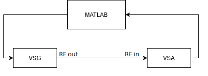
You can verify the generated output by using the vector signal analyzer (VSA) on the VST, when configured as a loopback, as illustrated.
Configure VSA
Set the following parameters to the specified value.
Reference clock to onboard clock
Acquisition type to I/Q data
The reference level to -10 dBm
Carrier frequency to the radar center frequency
Acquisition rate to the sampling frequency
vsa = ividev("niRFSA", deviceID, "IDQuery", true, "ResetDevice", true);
ch = "0";
configureRefClock(vsa, "OnboardClock", 1e7);
configureAcquisitionType(vsa, "IQ");
configureReferenceLevel(vsa, ch, -10);
configureIQCarrierFrequency(vsa, ch, fc);
configureIQRate(vsa, ch, fs);
Configure the VSA to acquire enough samples to ensure that a complete pulse train is obtained.
finiteSamples = true;
numSamples = 2*lenTrain;

configureNumberOfSamples(vsa, ch, finiteSamples, numSamples);
Start Generation and Acquisition
To fetch IQ data, first start the acquisition, and then start the generation.
initiate(vsa)
initiate(vsg)
configureOutputEnabled(vsg, true);

[iData, qData, waveformSplit] = fetchIQSingleRecordSplitF64(vsa, "", 0, numSamples, 10);
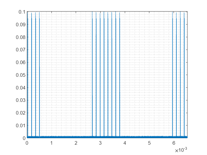
Extract information related to the plot from the waveform information.
t0 = waveformSplit.relativeInitialX;
tincr = waveformSplit.xIncrement;
k = double(waveformSplit.actualSamples);
t = t0 + tincr.*(0:k-1);

figure
plot(t, abs(complex(iData, qData)));
axis tight; grid minor
Clean Up
configureOutputEnabled(vsg, false);
abort(vsg);
abort(vsa);
Reducing Memory Footprint
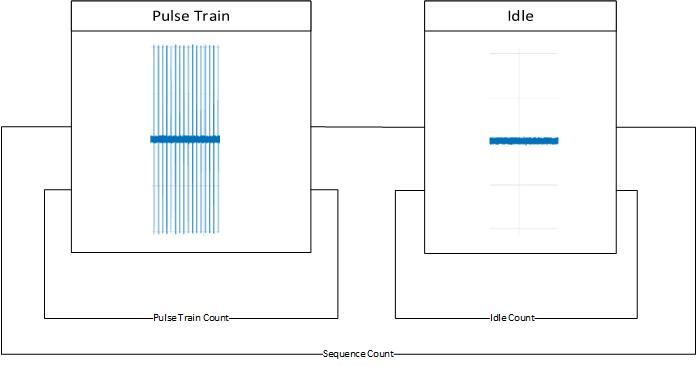
Scripting Pulse Train
Without scripting, you need enough memory for multiple pulse trains. With scripting, you need only a single pulse segment and an idle time segment, reducing memory requirements.
lengthFullWaveform = length(pulseTrain);
lengthSinglePulseTrainFull = length(singleWaveform) + length(idleSamples);
sizeReductionFullIdle = 100 * (1 - lengthSinglePulseTrainFull / lengthFullWaveform);
Scripting Idle Time
To determine a reduction factor, n, consider the following criteria:
It is significantly smaller than the size of the idle waveform.
It divides the length of the idle waveform with no remainder.
It meets or exceeds the size of the smallest allowable waveform (for NI PXI-5841, this is 8). To see how to determine this value programmatically, refer to the following code.
The driver must be able to keep up with the generation. This may require being significantly larger than the smallest allowable waveform.
lengthPulseTrainReduced = length(singleWaveform) + n;
sizeReductionPartialIdle = 100 * (1 - lengthPulseTrainReduced / lengthFullWaveform);

usageFull = [lengthFullWaveform; 100];
usageSinglePulse = [lengthSinglePulseTrainFull; floor(100-sizeReductionFullIdle)];
usagePartialIdle = [lengthPulseTrainReduced; floor(100-sizeReductionPartialIdle)];
usageTable = table(usageFull, usageSinglePulse, usagePartialIdle);
usageTable.Properties.RowNames = ["Number of Samples", "Percent (Full)"];
usageTable.Properties.VariableNames = ["Full Waveform", "Scripted Pulse", "Fully Scripted"];
format long
disp(usageTable)
                         Full Waveform    Scripted Pulse    Fully Scripted
                         _____________    ______________    ______________

    Number of Samples       2624000          1728000            129000
    Percent (Full)              100               65                 4
How to Script Idle Time (Considerations)
To review the waveform capabilities, including the minimum waveform size and waveform quantum, refer to the following code.
disp(vsg.Arb.WaveformCapabilities)
Clean Up
clear vsa vsg