Dynamic Spectrum Sharing for 5G NR and LTE Coexistence
This example shows how to generate a waveform containing LTE and 5G NR waveforms for dynamic spectrum sharing (DSS) by using LTE Toolbox™ and 5G Toolbox™.
Introduction
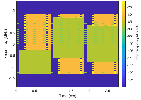
Dynamic spectrum sharing allows 5G and LTE to share resources dynamically in the same spectrum. Therefore, 5G can use the existing LTE spectrum without the need for re-farming existing bands. 5G and LTE coexistence also maximizes system efficiency because the LTE and 5G base stations, eNodeB and gNodeB, respectively, can use all available resources at all times. This figure shows an example in which the gNodeB scheduler allocates 5G resources dynamically every millisecond, filling all the resources unused by LTE. Specifically, the figure shows the spectrogram of the combined LTE and 5G waveform, in which the LTE waveform is in shades of green and the 5G waveform is in shades of yellow.
The main requirement of DSS is backward compatibility. That is, LTE devices must function as normal regardless of whether DSS is implemented. Specifically, 5G waveforms in DSS must not interfere with LTE always-on signals and channels, such as the cell reference signal (CRS), primary synchronization signal (PSS), secondary synchronization signal (SSS), and physical broadcast channel (PBCH). The 5G and LTE scheduling of resources can change dynamically every subframe, which is the lowest common time unit between the two technologies.
This example shows how to generate a waveform containing:
5G physical downlink shared channel (PDSCH)
LTE CRS
LTE PSS
LTE SSS
LTE PBCH
LTE physical downlink control channel (PDCCH)
LTE physical control format indicator channel (PCFICH)
LTE physical hybrid ARQ indicator channel (PHICH)
The 5G PDSCH occupies all resources unused by the LTE waveform. The example implements these techniques to enable DSS.
Perform rate-matching of the 5G PDSCH around the resource elements (REs) used by the LTE CRS. The higher layer parameter
RateMatchPatternLTE-CRS, defined in TS 38.331 Section 6.3.2, contains the information needed by the gNodeB to rate-match the PDSCH around the CRS.Reserve 5G PDSCH physical resource blocks (PRBs) that are occupied by the LTE PBCH, PSS, and SSS.
Use Rel-16 alternative locations for the 5G PDSCH demodulation reference signal (DM-RS), as described in TS 38.211 Section 7.4.1.1.2, for a 5G PDSCH configuration with: mapping type A, the first DM-RS allocated in symbol 3, and an additional DM-RS.
Allocate the 5G PDSCH starting from symbol 3 of each slot to ensure that the 5G PDSCH never collides with LTE control information channels.
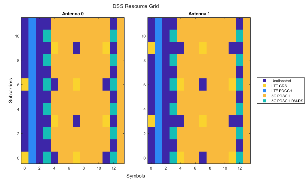
This figure shows an example resource grid for a single PRB and single subframe containing the LTE CRS, LTE PDCCH, and 5G PDSCH with its DM-RS. The LTE configuration consists of two CRS ports and the PDCCH scheduled in symbol 1. The 5G PDSCH configuration consists of two layers, mapping type A, allocated symbols from 3 to 13, a DM-RS in symbol 3, and an additional DM-RS. The figure shows the 5G PDSCH rate-matching around the REs allocated for the LTE CRS and the additional DM-RS allocated in symbol 12, instead of 11, to avoid collisions with the LTE CRS in antenna 1.
Waveform Configuration
Configure the LTE and 5G waveforms. You can change the length of the generated waveform, the bandwidth of 5G and LTE carriers in terms of number of PRBs, the number of ports for the LTE CRS, the shifting value for assigning the LTE cell identity, and the LTE carrier offset to NR point A. Set the LTE carrier offset to NR point A in units of 15 kHz subcarriers, as discussed in TS 38.214 Section 5.1.4.2.
numSubframes =10; % Number of subframes gnbNumPRB =
52; % Size of 5G carrier in number of PRBs (1...275) enbNumPRB =
25; % Size of LTE carrier in number of PRBs enbNumCRSPorts =
2; % Number of LTE CRS ports enbVShift =
0; % LTE shifting value v-Shift enbCarrierFrequency =
0; % LTE carrier offset to NR point A, in units of 15 kHz subcarriers (0...16383)
Initialize the random number generator to its default value for reproducibility.
rng("default");LTE Configuration
Configure the cell-wide settings for LTE.
enb = getLTEConfig(enbNumPRB,enbNumCRSPorts,enbVShift,enbCarrierFrequency,numSubframes);
5G Configuration
Configure the cell-wide settings for 5G considering a subcarrier spacing of 15 kHz. This value of the subcarrier spacing ensures that the 5G waveform has the same time-frequency OFDM structure as the LTE waveform.
gnb = nrCarrierConfig;
gnb.NSizeGrid = gnbNumPRB;
disp(gnb)
  nrCarrierConfig with properties:

                NCellID: 1
      SubcarrierSpacing: 15
           CyclicPrefix: 'normal'
              NSizeGrid: 52
             NStartGrid: 0
                  NSlot: 0
                 NFrame: 0
    IntraCellGuardBands: [0×2 double]

   Read-only properties:
         SymbolsPerSlot: 14
       SlotsPerSubframe: 1
          SlotsPerFrame: 10
5G PDSCH Configuration
Configure the 5G PDSCH to occupy all the resources available and unused by the LTE transmission. In particular, symbol 3 is the first symbol allocated for the PDSCH. This choice is intentionally conservative because the PCFICH, PHICH, and PDCCH in LTE can occupy up to the first three symbols in a subframe.
pdsch = nrPDSCHConfig;
pdsch.PRBSet = 0:gnb.NSizeGrid-1;      % Full-band allocation
pdsch.SymbolAllocation = [3 11];       % Full-slot allocation, starting from symbol 3
pdsch.MappingType = "A";               % PDSCH mapping type A
pdsch.DMRS.DMRSTypeAPosition = 3;      % First DM-RS in symbol 3 for PDSCH mapping type A
pdsch.DMRS.DMRSAdditionalPosition = 1; % Additional DM-RS position
For a 5G PDSCH mapping type A configured with a DM-RS on symbol 3 and an additional DM-RS, the second DM-RS collides with the LTE CRS on some REs. To avoid collision between the 5G PDSCH DM-RS and the LTE CRS, TS 38.211 Section 7.4.1.1.2 defines an alternative DM-RS location, moving the allocation of the second DM-RS from symbol 11 to symbol 12. The option of using an alternative DM-RS location is subject to UE capability, as specified in TS 38.306 Section 4.2.7.5. The example sets the alternative DM-RS location by using the CustomSymbolSet property of the nrPDSCHDMRSConfig (5G Toolbox) object.
if (pdsch.MappingType == "A") && ...
        (pdsch.DMRS.DMRSAdditionalPosition == 1) && ...
        (pdsch.DMRS.DMRSTypeAPosition == 3)
    pdsch.DMRS.CustomSymbolSet = [3 12];
end
Compute the indices occupied by the LTE CRS in the 5G numerology and assign them to the ReservedRE property of the nrPDSCHConfig (5G Toolbox) object. This property specifies the RE indices that are unavailable for the PDSCH.
pdsch.ReservedRE = getReservedRE(enbNumPRB,enbNumCRSPorts,enbVShift,enbCarrierFrequency,gnb);
Compute the PRBs occupied by the LTE PBCH and synchronization signals (PSS and SSS) in the 5G numerology and assign them to the ReservedPRB property of the nrPDSCHConfig object. This property specifies the PRB and symbol patterns that are unavailable for the PDSCH.
pdsch.ReservedPRB = getReservedPRB(enb,gnb);
Define the power scaling for each channel and signal in dB. The example chooses these values solely to ease the visualization of each channel and signal in the spectrogram view.
pdschPower = 15;     % PDSCH power scaling in dB
pdschDMRSPower = 18; % PDSCH DM-RS power scaling in dB
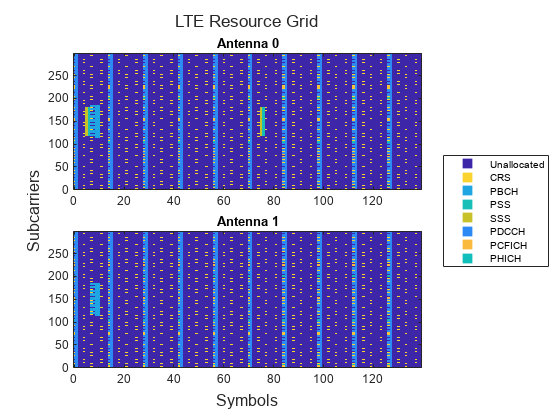
LTE Waveform Generation
Generate the LTE waveform, resource grid, and information output. The LTE waveform contains:
Always-on signals CRS, PSS, and SSS.
Always-on channel PBCH.
PCFICH, PHICH, and PDCCH.
[enbWave,enbGrid] = lteRMCDLTool(enb,[1;0;0;1]);
enbInfo = lteOFDMInfo(enb);
Plot the LTE resource grid.
enbChannelNames = ["CRS","PBCH","PSS","SSS","PDCCH","PCFICH","PHICH"];
plotResourceGrid(enb,enbGrid,numSubframes,enbChannelNames);
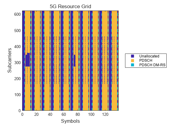
5G Waveform Generation
Generate the 5G waveform containing the PDSCH and its DM-RS.
Define the total number of slots.
numSlots = numSubframes*gnb.SlotsPerSubframe;
Initialize an empty resource grid.
gnbGrid = [];
Loop over the total number of slots to generate the 5G resource grid.
for nslot = 0:numSlots-1

    % Update the carrier slot number and create an empty resource grid for
    % the current slot
    gnb.NSlot = nslot;
    gridSlot = nrResourceGrid(gnb,pdsch.NumLayers);

    % Get the PDSCH and PDSCH DM-RS indices and symbols
    [pdschIndices,pdschIndicesInfo] = nrPDSCHIndices(gnb,pdsch);
    cw = randi([0 1],pdschIndicesInfo.G,1);
    pdschSymbols = nrPDSCH(gnb,pdsch,cw) * db2mag(pdschPower);
    pdschDMRSIndices = nrPDSCHDMRSIndices(gnb,pdsch);
    pdschDMRSSymbols = nrPDSCHDMRS(gnb,pdsch) * db2mag(pdschDMRSPower);

    % Place the symbols in the grid
    gridSlot(pdschIndices) = pdschSymbols;
    gridSlot(pdschDMRSIndices) = pdschDMRSSymbols;

    % Append the resource grid for the current slot to the overall resource
    % grid
    gnbGrid = cat(2,gnbGrid,gridSlot);

end
Plot the 5G resource grid.
gnbChannelNames = ["PDSCH","PDSCH DM-RS"];
plotResourceGrid(struct("gnb",gnb,"pdsch",pdsch),gnbGrid,numSubframes,gnbChannelNames);
Generate the 5G waveform by performing OFDM modulation on the resource grid.
[gnbWave,gnbInfo] = nrOFDMModulate(gnb,gnbGrid,Windowing=0);
Generate Combined DSS Waveform
Shift the LTE waveform according to the value of enbCarrierFrequency.
enbfotx = comm.PhaseFrequencyOffset;
enbfotx.SampleRate = enbInfo.SamplingRate;
enbfotx.FrequencyOffset = enbCarrierFrequency*15e3; % Hz
enbWave = enbfotx(enbWave);
If LTE and 5G sample rates are different, resample the waveform with the lowest sample rate to the highest sample rate.
enbSR = enbInfo.SamplingRate;
gnbSR = gnbInfo.SampleRate;
if gnbSR >= enbSR
    enbWave = resample(enbWave,gnbSR,enbSR);
    ofdmInfo = gnbInfo;
else
    gnbWave = resample(gnbWave,enbSR,gnbSR);
    ofdmInfo = enbInfo;
end
Combine the two waveforms.
wave = enbWave + gnbWave;
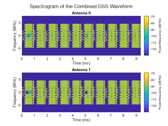
Spectrogram of Combined DSS Waveform
Plot the spectrogram of the combined waveform. You can see the LTE and 5G waveforms coexisting in the same spectrum.
plotDSSSpectrogram(wave,ofdmInfo,enbSR,gnbSR,numSubframes);
References
[1] 3GPP TS 38.211. “NR; Physical channels and modulation.” 3rd Generation Partnership Project; Technical Specification Group Radio Access Network.
[2] 3GPP TS 38.214. “NR; Physical layer procedures for data.” 3rd Generation Partnership Project; Technical Specification Group Radio Access Network.
[3] 3GPP TS 38.306. “NR; User Equipment (UE) radio access capabilities.” 3rd Generation Partnership Project; Technical Specification Group Radio Access Network.
[4] 3GPP TS 38.331. "NR; Radio Resource Control (RRC) protocol specification.” 3rd Generation Partnership Project; Technical Specification Group Radio Access Network.
Local Functions
 function enb = getLTEConfig(numPRB,numCRSPorts,vShift,carrierFrequency,numSubframes)
    % Generate the cell-wide configuration for LTE, given the number of
    % PRBs, the number of CRS ports, the shifting value v-Shift for the LTE
    % CRS, and the carrier frequency offset from point A.

    % Define the LTE configuration
    enb = struct();
    enb.NDLRB = numPRB;
    enb.CellRefP = numCRSPorts;
    enb.NCellID = vShift;
    enb.CyclicPrefix = "Normal";
    enb.CFI = 2;
    enb.Ng = "Sixth";
    enb.PHICHDuration = "Normal";
    enb.NFrame = 0;
    enb.NSubframe = 0;
    enb.TotSubframes = numSubframes;
    enb.DuplexMode = "FDD";
    if numCRSPorts>1
        enb.PDSCH.TxScheme = "SpatialMux";
    end
    enb.CarrierFrequency = carrierFrequency;

    % Define the power scaling of LTE signals and channels.
    % These values are chosen solely to ease the visualization of each
    % channel and signal in the spectrogram view.
    enb.PDSCH.PDCCHPower = 24;
    enb.PCFICHPower = 12;
    enb.PHICHPower = 30;
    % To make sure that the LTE waveform contains PDCCH but not PDSCH, set
    % the PDSCH power resource element allocation so that the content of
    % the PDSCH does not affect the LTE waveform
    enb.PDSCH.Rho = -inf;
end

function ind = getReservedRE(numPRB,numCRSPorts,vShift,carrierFrequency,gnb)
    % Compute the REs used by the LTE CRS that the 5G PDSCH needs to
    % rate-match around.

    % Get the LTE configuration for the rate-matching around the CRS
    enb = struct();
    enb.NDLRB = numPRB;
    enb.CellRefP = numCRSPorts;
    enb.NCellID = vShift;
    enb.CarrierFrequency = carrierFrequency;
    enb.CyclicPrefix = "Normal";
    enb.DuplexMode = "FDD";

    % Get the RE indices for the CRS
    ind = getLTEREIndices(enb,gnb,"CRS");
end

function prbs = getReservedPRB(enb,gnb)
    % Compute the physical resource blocks used by the LTE PBCH, PSS, and
    % SSS that the 5G PDSCH needs to rate-match around.

    % Initialize empty nrPDSCHReservedConfig objects to store the reserved
    % PRBs. The example defines two objects because the periodicity of the
    % PBCH is different from that of the PSS and SSS.
    prbs = {nrPDSCHReservedConfig,nrPDSCHReservedConfig};

    % Compute the 5G BWP grid size
    gnbSize = size(nrResourceGrid(gnb));

    % Get the RE indices for the PBCH and convert them to subscript
    pbchInd = getLTEREIndices(enb,gnb,"PBCH");
    [pbchREInd,pbchSymbInd] = ind2sub(gnbSize,pbchInd);

    % Store the reserved PRBs for the LTE PBCH. Set the period considering
    % that the PBCH is transmitted in subframe 0 of each frame.
    prbInd = unique(floor(pbchREInd/12)); % 0-based PRBs associated to the RE indices
    prbs{1}.PRBSet = prbInd;
    prbs{1}.SymbolSet = unique(pbchSymbInd-1); % 0-based
    prbs{1}.Period = 10*gnb.SlotsPerSubframe;

    % Get the RE indices for the PSS and SSS and convert them to subscript
    ssInd = getLTEREIndices(enb,gnb,["PSS","SSS"]);
    [ssREInd,ssSymbInd] = ind2sub(gnbSize,ssInd);

    % Store the reserved PRBs for the LTE synchronization signals PSS and
    % SSS. Set the period considering that the PSS and SSS are transmitted
    % in subframes 0 and 5 of each frame.
    prbInd = unique(floor(ssREInd/12)); % 0-based PRBs associated to the RE indices
    prbs{2}.PRBSet = prbInd;
    prbs{2}.SymbolSet = unique(ssSymbInd-1); % 0-based
    prbs{2}.Period = 5*gnb.SlotsPerSubframe;
end

function ind = getLTEREIndices(enb,gnb,signalName)
    % Compute the REs used by LTE always-on signals (CRS, PBCH, PSS, and
    % SSS) that the 5G PDSCH needs to rate-match around.

    % enb frequency indices 'enbf' in terms of 15 kHz subcarrier spacing
    enbSize = lteResourceGridSize(enb);
    enbK = enbSize(1);
    enbf = [-enbK/2:-1 1:enbK/2].' + enb.CarrierFrequency;

    % gnb frequency indices 'gnbf' in terms of 15 kHz subcarrier spacing
    gnbSize = size(nrResourceGrid(gnb));
    gnbK = gnbSize(1);
    gnbf = (-gnbK/2:(gnbK/2 - 1)).';
    gnbf = gnbf(gnb.NStartGrid*12 + (1:gnbK));

    % Compute the CRS indices
    crsIndices = [];
    if any(signalName=="CRS")
        crsIndices = lteCellRSIndices(enb,"sub");
    end
    % Compute the PBCH indices
    pbchIndices = [];
    if any(signalName=="PBCH")
        pbchIndices = ltePBCHIndices(enb,"sub");
    end
    % Compute the PSS indices
    pssIndices = [];
    if any(signalName=="PSS")
        pssIndices = ltePSSIndices(enb,0,"sub");
    end
    % Compute the SSS indices
    sssIndices = [];
    if any(signalName=="SSS")
        sssIndices = lteSSSIndices(enb,0,"sub");
    end
    % Create the list of all indices
    indTot = [crsIndices; pbchIndices; pssIndices; sssIndices];
    enbk = indTot(:,1);
    enbl = indTot(:,2);

    enbf = enbf(enbk);

    gnbk = arrayfun(@(x)find(gnbf==x),enbf,UniformOutput=false);
    z = cellfun(@isempty,gnbk);
    gnbk = cat(1,zeros(0,1),gnbk{:});

    gnbl = enbl;
    gnbl(z) = [];

    ind = sub2ind(gnbSize,gnbk,gnbl);
    ind = ind - 1; % 1-based to 0-based
end

function plotResourceGrid(in,grid,numSubframes,chNames)
    % Plot the resource grid for each antenna.

    if isfield(in,"CellRefP") % LTE
        isLTE = 1;
        nsf = numSubframes;
        enb = in;
        numPorts = enb.CellRefP;
    else % 5G
        isLTE = 0;
        gnb = in.gnb;
        pdsch = in.pdsch;
        nsf = numSubframes* gnb.SlotsPerSubframe;
        numPorts = pdsch.NumLayers;
    end
    chNames = ["Unallocated" chNames];

    % Define channel power levels
    chplevel.Unallocated = 0;   % Unallocated REs
    chplevel.CRS = 0.9;         % LTE CRS
    chplevel.PBCH = 0.39;       % LTE PBCH
    chplevel.PSS = 0.51;        % LTE PSS
    chplevel.SSS = 0.75;        % LTE SSS
    chplevel.PDCCH = 0.3;       % LTE PDCCH
    chplevel.PCFICH = 0.83;     % LTE PCFICH
    chplevel.PHICH = 0.5;       % LTE PHICH
    chplevel.PDSCH = 0.83;      % 5G PDSCH
    chplevel.PDSCH_DMRS = 0.45; % 5G PDSCH DM-RS

    % Generate the resource grid for plotting
    rbGrid = [];
    gridSize = size(grid);
    gridSize(2) = gridSize(2)/nsf; % Length of a single subframe or slot
    for ns = 0:nsf-1 % Loop over each LTE subframe or 5G slot
        % Initialize an empty grid for the current subframe or slot
        rbGridS = zeros(gridSize);

        % Populate the grid
        if isLTE
            enb.NSubframe = mod(ns,10);

            rbGridS(lteCellRSIndices(enb)) = chplevel.CRS;
            rbGridS(ltePSSIndices(enb)) = chplevel.PSS;
            rbGridS(lteSSSIndices(enb)) = chplevel.SSS;
            rbGridS(ltePBCHIndices(enb)) = chplevel.PBCH;
            rbGridS(ltePCFICHIndices(enb)) = chplevel.PCFICH;
            rbGridS(ltePHICHIndices(enb)) = chplevel.PHICH;
            rbGridS(ltePDCCHIndices(enb)) = chplevel.PDCCH;

        else % 5G
            gnb.NSlot = mod(ns,10);

            rbGridS(nrPDSCHIndices(gnb,pdsch)) = chplevel.PDSCH;
            rbGridS(nrPDSCHDMRSIndices(gnb,pdsch)) = chplevel.PDSCH_DMRS;
        end

        % Append the resource grid for the current subframe or slot to the
        % overall resource grid
        rbGrid = cat(2,rbGrid,rbGridS);
    end

    % Define the colormap and the scaling needed for the plot
    cmap = parula(256);
    chpval = struct2cell(chplevel);
    cscaling = length(cmap);
    fnames = strrep(fieldnames(chplevel),"_"," ");
    fnames = strrep(fnames,"DMRS","DM-RS");
    chpval = chpval(contains(fnames,chNames));
    clevels = floor(cscaling*[chpval{:}]);

    % Define the plot title
    if isLTE
        figTitle = "LTE Resource Grid";
    else
        figTitle = "5G Resource Grid";
    end
    plotTitle = "Antenna ";

    % Define the axes limits for the plot to be 0-based
    minX = 0;
    maxX = size(rbGrid,2)-1;
    minY = 0;
    maxY = size(rbGrid,1)-1;

    % Plot the resource grid for each port or layer
    fh = figure;
    t = tiledlayout(fh,"flow",TileSpacing="Compact");
    for idx = 1:numPorts
        nexttile;
        ax = gca;
        img = image(ax,cscaling*abs(rbGrid(:,:,idx)));
        img.XData = minX:maxX; % 0-based symbol number
        img.YData = minY:maxY; % 0-based subcarrier number
        axis(ax,[minX-0.5 maxX+0.5 minY-0.5 maxY+0.5]);
        axis(ax,"xy");
        if numPorts>1
            title(ax,plotTitle+num2str(idx-1)); % 0-based antenna number
        end
        colormap(ax,cmap);
    end
    title(t,figTitle);
    xlabel(t,"Symbols");
    ylabel(t,"Subcarriers");

    % Create the legend
    N = length(clevels);
    p = struct(Marker="s",LineStyle="none",MarkerSize=8,LineWidth=1.25);
    L = line(ax,NaN(N),NaN(N),p); % Generate markers
    % Index the color map and associate the selected colors with the markers
    c = mat2cell([cmap(1,:);cmap(clevels(2:end),:)],ones(1,N),3);
    set(L,{"color"},c); %#ok<STRSCALR>
    set(L,{"MarkerFaceColor"},c); %#ok<STRSCALR>
    lg = legend(ax,chNames{:});
    lg.Layout.Tile = "East";
end

function plotDSSSpectrogram(wave,ofdmInfo,enbSR,gnbSR,numSubframes)
    % Plot the spectrogram of the combined waveform.

    % To minimize the artifacts shown in the spectrogram and due to out of
    % band leakage of the resampled waveform, adjust the waveform to
    % consider the filter response.
    cpLengths = double(ofdmInfo.CyclicPrefixLengths);
    OSR = max(enbSR/gnbSR,gnbSR/enbSR);
    n = min(10,floor(max(cpLengths)/(2*OSR)));
    order = 2*n*OSR; % Order of the filter used during resampling
    wave = circshift(wave,order/2);

    fh = figure;
    t = tiledlayout(fh,"flow",TileSpacing="Compact");
    % Compute the cyclic prefixes to remove from the waveform for each
    % subframe.
    nfft = double(ofdmInfo.Nfft);
    if isfield(ofdmInfo,'SampleRate')
        sampleRate = ofdmInfo.SampleRate;
    else
        sampleRate = ofdmInfo.SamplingRate;
    end
    symbolLengths = nfft+cpLengths;
    cpidxs = arrayfun(@(x,y)(x+(1:y)),cumsum([0 symbolLengths(1:end-1)]),cpLengths,UniformOutput=false);
    cpidxs = [cpidxs{:}];
    sfWaveLength = sampleRate/1000;

    % Loop over each antenna
    for idx = 1:size(wave,2)
        nexttile;
        txWaveNoCP = [];
        for nsf = 1:numSubframes
            waveNoCP = wave(1+(nsf-1)*sfWaveLength:nsf*sfWaveLength,idx);
            waveNoCP(cpidxs) = []; % Remove the cyclic prefix in this subframe
            txWaveNoCP = cat(1,txWaveNoCP, waveNoCP);
        end
        spectrogram(txWaveNoCP,ones(nfft,1),0,nfft,"centered",sampleRate,"yaxis",MinThreshold=-130);
        title(['Antenna ' num2str(idx-1)]); % 0-based antenna number
    end
    title(t,"Spectrogram of the Combined DSS Waveform");
end
See Also
Functions
Objects
nrPDSCHConfig(5G Toolbox)
Topics
- 5G NR Downlink Vector Waveform Generation (5G Toolbox)
- 5G NR Uplink Vector Waveform Generation (5G Toolbox)
- 5G NR-TM and FRC Waveform Generation (5G Toolbox)