FDD and TDD Duplexing
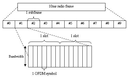
The LTE Toolbox™ product can generate and manipulate signals for the duplexing arrangements specified in the LTE standard. In LTE, downlink and uplink transmissions are organized into radio frames of duration 10ms consisting of 10 consecutive subframes, each consisting of a number of consecutive OFDM symbols, as shown in the following figure.
Create Resource Grid for Cyclic Prefix Choice
This example shows how to create a resource grid for either normal or extended cyclic prefix. The number of OFDM symbols within one subframe is either 14 for normal cyclic prefix, or 12 for extended cyclic prefix.
Create the cell-wide settings structure.
enb.CyclicPrefix = 'Normal';
enb.NDLRB = 9;
enb.CellRefP = 1;
Get subframe resource grid dimensions.
dims = lteDLResourceGridSize(enb)
dims = 1×3

   108    14     1
Switch to extended cyclic prefix.
enb.CyclicPrefix = 'Extended';
dims = lteDLResourceGridSize(enb)
dims = 1×3
108 12 1
The second dimension of the output of lteDLResourceGridSize is the number of symbols in the subframe.
Create Frame with CellRS in Subframes
This example shows how to create a frame containing the cell-specific reference signals (CellRS) in each subframe. The radio frame is represented in the LTE Toolbox™ product by the use of a succession of 10 cell-wide settings structures with the NSubframe field set from 0 through 9 in each case.
Initialize Cell-wide Setting Structure and Create Empty Resource Grid
Modify the NDLRB parameter to set the number of resource blocks. Modify CellRefP to set one transmit antenna port. Modify NCellID to set the cell ID. Specify normal cyclic prefix and antenna port zero.
enb.NDLRB = 6;
enb.CellRefP = 1;
enb.NCellID = 1;
enb.CyclicPrefix = 'Normal';
antenna = 0;
Create an empty resource grid to be populated with subframes.
txGrid = [];
Populate Resource Grid for Each Subframe
Create an empty resource grid for each subframe and set the current subframe number.
Generate cell-specific reference signal symbols and indices.
Map the cell-specific reference signal to the grid and append the subframe to the grid to be transmitted.
for sf = 0:9
    subframe = lteDLResourceGrid(enb);
    enb.NSubframe = sf;
    cellRsSym = lteCellRS(enb,antenna);
    cellRsInd = lteCellRSIndices(enb,antenna);
    subframe(cellRsInd) = cellRsSym;
    txGrid = [txGrid subframe];
end
Frame Structure Type 1: FDD
In the FDD duplexing mode, all 10 subframes within a radio frame contain downlink or uplink subframes depending on the link direction.
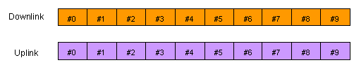
The uplink and downlink transmitters have separate bandwidths in which to make their transmissions. Therefore, each can transmit at all times.
Within the LTE Toolbox product, you can create signals
or indices for FDD duplexing mode simply by setting the NSubframe field
of the cell-wide settings structure to the appropriate subframe number.
Functions whose behavior depends on the duplexing mode have the DuplexMode field,
which you can set to 'FDD' or 'TDD'.
If you do not specify this field, 'FDD' is used
by default.
Generate PSS Indices for FDD Mode
This example shows how to generate the primary synchronization signal (PSS) indices in subframe 0 using the FDD duplexing mode.
First, create the cell-wide settings structure.
enb.CyclicPrefix = 'Normal';
enb.NDLRB = 9;
enb.NCellID = 1;
enb.NSubframe = 0;
enb.DuplexMode = 'FDD';
Next, create PSS indices, display size and the first five indices in subframe 0.
ind = ltePSSIndices(enb);
size(ind)
ans = 1×2

    62     1
ind(1:5)
ans = 5×1 uint32 column vector

   672
   673
   674
   675
   676
If the same call is made for subframe 1 instead, then the result is an empty matrix.
enb.NSubframe = 1;
An empty matrix indicates that the PSS is not present in subframe 1. By calling the functions for indices and values for subframes 0 through to 9 by setting the NSubframe field, the appropriate transmissions across a radio frame can be formed.
ind = ltePSSIndices(enb)
ind =

  0×1 empty uint32 column vector
Frame Structure Type 2: TDD
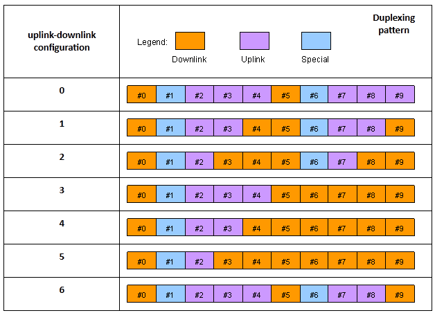
In the TDD duplexing mode, a single bandwidth is shared between uplink and downlink, with the sharing being performed by allotting different periods of time to uplink and downlink. In LTE, there are 7 different patterns of uplink-downlink switching, termed uplink-downlink configurations 0 through 6, as shown in the following figure.
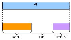
The special subframe (subframe 1 in every uplink-downlink configuration, and subframe 6 in uplink-downlink configurations 0, 1, 2 and 6) contains a portion of downlink transmission at the start of the subframe (the Downlink Pilot Time Slot, DwPTS), a portion of unused symbols in the middle of the subframe (the Guard Period) and a portion of uplink transmission at the end of the subframe (the Uplink Pilot Time Slot, UpPTS), as shown in the following figure.
The lengths of DwPTS, GP, and UpPTS can take one of 10 combinations of values, termed special subframe configurations 0 through 9. The LTE standard, TS 36.211 Table 4.2-1, specifies the lengths in terms of the fundamental period of the OFDM modulation, but the lengths can be interpreted in terms of OFDM symbols as shown in the following table.
| Configuration of special subframe (lengths of DwPTS/GP/UpPTS) | ||||||
|---|---|---|---|---|---|---|
| Special Subframe Configuration | Normal cyclic prefix in downlink | Extended cyclic prefix in downlink | ||||
| DwPTS | UpPTS | DwPTS | UpPTS | |||
| Normal cyclic prefix in uplink | Extended cyclic prefix in uplink | Normal cyclic prefix in uplink | Extended cyclic prefix in uplink | |||
| 0 | 3 | 1 | 1 | 3 | 1 | 1 |
| 1 | 9 | 8 | ||||
| 2 | 10 | 9 | ||||
| 3 | 11 | 10 | ||||
| 4 | 12 | 3 | 2 | 2 | ||
| 5 | 3 | 2 | 2 | 8 | ||
| 6 | 9 | 9 | ||||
| 7 | 10 | 5 | ||||
| 8 | 11 | - | - | - | ||
| 9 | 6 | - | - | - | ||
Thus, in effect, the special subframe is both a downlink subframe and an uplink subframe, with some restriction placed on the number of OFDM symbols that are occupied in each case.
To specify TDD operation, in the cell-wide settings structure,
set the optional DuplexMode field to 'TDD'.
When you use this setting, functions that require DuplexMode also
require that you specify the uplink-downlink configuration (0,…,6)
in the TDDConfig field, the subframe number in
the NSubframe field, and the special subframe
configuration (0,…,9) in the SSC field.
Generate CellRS Indices for TDD Mode
This example shows how to create the subscripts for the positions of the cell-specific reference signal (CellRS) for antenna port 0 in subframe 6 for uplink-downlink configuration 2 and special subframe configuration 4 with extended cyclic prefix.
First, create the parameter structure.
enb.NDLRB        = 9;
enb.NCellID      = 1;
enb.DuplexMode   = 'TDD';
enb.NSubframe    = 6;
enb.TDDConfig    = 2;
enb.SSC          = 4;
enb.CyclicPrefix = 'Extended';
Next, create the cell-specific RS indices.
sub = lteCellRSIndices(enb,0,'sub')sub = 18×3 uint32 matrix
2 1 1
8 1 1
14 1 1
20 1 1
26 1 1
32 1 1
38 1 1
44 1 1
50 1 1
56 1 1
62 1 1
68 1 1
74 1 1
80 1 1
86 1 1
⋮
The second column, which gives the OFDM symbol number (1-based) within the subframe, has values of 1 indicating that only the 1st OFDM symbol will contain cell-specific reference signals in this case. This is because the chosen subframe is a special subframe with DwPTS of length 3 and therefore the other cell-specific reference signal elements (in OFDM symbols 4, 7 and 10) which would be present in full downlink subframes are not generated.
To confirm this theory, change the duplex mode to FDD.
enb.DuplexMode   = 'FDD';
sub = lteCellRSIndices(enb,0,'sub');
unique(sub(:,2))
ans = 4×1 uint32 column vector

    1
    4
    7
   10
In this case, the switch over to FDD means that the now irrelevant fields, TDDConfig and SSC, are ignored.
Dimension Information Related to Duplexing
This example shows how to extract information from a parameter structure. To facilitate working with different duplexing arrangements, the LTE Toolbox™ product provides the lteDuplexingInfo information function. This function takes a cell-wide settings structure containing the fields mentioned in the preceding sections. It returns a structure that indicates the type of the current subframe and the number of symbols in the current subframe.
First, create a parameter structure.
%   Copyright 2026 The MathWorks, Inc.

enb.NDLRB        = 9;
enb.NCellID      = 1;
enb.DuplexMode   = 'TDD';
enb.NSubframe    = 6;
enb.TDDConfig    = 2;
enb.SSC          = 4;
enb.CyclicPrefix = 'Extended';
Next, extract the dimension information.
lteDuplexingInfo(enb)
ans = struct with fields:
     SubframeType: 'Special'
         NSymbols: 12
       NSymbolsDL: 3
    NSymbolsGuard: 7
       NSymbolsUL: 2
Finally, change the NSubframe property and extract the dimension information again.
enb.NSubframe    = 0;
lteDuplexingInfo(enb)
ans = struct with fields:
     SubframeType: 'Downlink'
         NSymbols: 12
       NSymbolsDL: 12
    NSymbolsGuard: 0
       NSymbolsUL: 0
This function provides direct access to the uplink-downlink configuration patterns via the SubframeType field and special subframe DwPTS, GP and UpPTS lengths via the NSymbolsDL, NSymbolsGuard, and NSymbolsUL fields.