LTE Sidelink Resource Pools and PSCCH Period
This example shows how sidelink direct communication resource pools and PSCCH periods are defined and parameterized. It shows the relationship between the semi-static RRC pool parameters and the PSCCH period structure. It also shows how the dynamic scheduling parameters (DCI and SCI) for transmission mode 1 and mode 2 affect the final transmission resource selection.
Introduction to ProSe Direct Communications and the Sidelink
Release 12 of the 3GPP LTE standard introduced a new device-to-device (D2D) interface aimed primarily at allowing LTE to support public safety communication systems. In terms of the overall LTE RAN, this interface enables two kinds of proximity based services (known in 3GPP as ProSe):
ProSe Direct Communication, where direct UE to multiple UE communication (group communication) is possible without data transmission on the uplink or downlink. This is allowed for public safety applications only and supports one or more UEs being out of coverage (network and/or frequency).
ProSe Direct Discovery, where business services can be enabled for UEs that are close to each other. This feature can be used for commercial applications (for example, service advertising) in the case when both UEs are in network coverage.
In terms of the lower stack, the LTE D2D interface is called the sidelink and, in terms of the system architecture, it is known as PC5 (in contrast to the UE/eNodeB interface, Uu). It comprises a collection of new physical signals, physical channels, transport channels and messages. Since the sidelink is transmitted by a UE, it is closely related to the uplink, but it also incorporates some aspects of downlink synchronization and control signaling. One significant result of this design is that a UE will now have to receive and generate uplink-style (sidelink).
This example focuses solely on direct communications, where the relevant sidelink physical layer channels and signals are,
Physical Sidelink Shared Channel (PSSCH)
Physical Sidelink Control Channel (PSCCH) (carrying SCI)
Physical Sidelink Broadcast Channel (PSBCH)
Sidelink Shared Channel (SL-SCH)
Sidelink Broadcast Channel (SL-BCH) (carrying MIB-SL)
Sidelink Synchronization Signals
In addition to the above channels, new physical layer procedures have been introduced as described in TS 36.213 Section 14. A key concept in these processes is that of a resource pool which defines the subset of available subframes and resource blocks for either sidelink transmission or reception. Sidelink communication is a half-duplex scheme and a UE can be configured with multiple transmit resource pools and multiple receive resource pools. The resource pools are configured semi-statically by layer 3 messaging. When data is to be sent using a resource pool, the actual transmission resources are selected dynamically from within the pool using one of two different modes:
Transmission mode 1 - the serving eNodeB specifies the resources via a DCI format 5 message sent to the transmitting UE. This mode requires the UE to be fully connected to the network (RRC_CONNECTED state).
Transmission mode 2 - the transmitting UE self-selects the resources according to rules aimed at minimizing the collision risk. This mode can be used when the UE is connected, idle (RRC_IDLE) or out-of-network coverage.
Introduction to Sidelink Resource Pools and PSCCH Period
A sidelink direct communication resource pool is configured on a semi-static basis using the layer 3 SL-CommResourcePool RRC message (TS 36.331 Section 6.3.8). The layer 1 physical resources (subframes and resource blocks) associated with the pool are partitioned into a sequence of repeating 'hyperframes' known as PSCCH periods. This is the standardized term used in TS 36.213 but it is also sometimes referred to as the SA (scheduling assignment) period or SC (sidelink control) period. Within a PSCCH period there are separate subframe pools and resource block pools for control (PSCCH) and data (PSSCH). The PSCCH subframes always precede those for PSSCH transmission. This is analogous to the symbol layout of the PDCCH and PDSCH OFDM symbols within a single downlink subframe, where the control region precedes the data part. The PSCCH carries sidelink control information (SCI) messages, which describe the dynamic transmission properties of the PSSCH that follow it. The receiving UE searches all configured PSCCH resource pools for SCI transmissions of interest to it. A UE can be a member of more than one sidelink communications group.
These subframe and resource block pools are defined by different parameters in the SL-CommResourcePool-r12 message. The ASN.1 definition of the message type (see TS 36.331 Section 6.1 for general terms) is given by,
SL-CommResourcePool-r12 ::= SEQUENCE {
sc-CP-Len-r12 SL-CP-Len-r12,
sc-Period-r12 SL-PeriodComm-r12,
sc-TF-ResourceConfig-r12 SL-TF-ResourceConfig-r12,
data-CP-Len-r12 SL-CP-Len-r12,
dataHoppingConfig-r12 SL-HoppingConfigComm-r12,
ue-SelectedResourceConfig-r12 SEQUENCE {data-TF-ResourceConfig-r12 SL-TF-ResourceConfig-r12,
trpt-Subset-r12 SL-TRPT-Subset-r12 OPTIONAL -- Need OP
} OPTIONAL, -- Need OR
rxParametersNCell-r12 SEQUENCE {tdd-Config-r12 TDD-Config OPTIONAL, -- Need OP
syncConfigIndex-r12 INTEGER (0..15)
} OPTIONAL, -- Need OR
txParameters-r12 SEQUENCE {sc-TxParameters-r12 SL-TxParameters-r12,
dataTxParameters-r12 SL-TxParameters-r12
} OPTIONAL, -- Cond Tx
...
}
This example uses a MATLAB structure to contain all the simulation parameters including those representing a subset of the SL-CommResourcePool-r12 message.
% This example bundles all parameters into a structure based on
% SL-CommResourcePool-r12. Compare this parameter structure with the RRC
% message definition from TS 36.331 Section 6.3.8
commpoolparameters = PSCCHPeriod.defaultConfig(1,'5MHz')
commpoolparameters =

  struct with fields:

                            NSLRB: 25
                       DuplexMode: 'FDD'
                        TDDConfig: 0
                       UESelected: 'On'
                       SyncEnable: 'On'
                     NPSCCHPeriod: 0
                    sc_CP_Len_r12: 'Normal'
                    sc_Period_r12: 40
         sc_TF_ResourceConfig_r12: [1×1 struct]
                  data_CP_Len_r12: 'Normal'
            dataHoppingConfig_r12: [1×1 struct]
    ue_SelectedResourceConfig_r12: [1×1 struct]
                       syncConfig: [1×1 struct]
Note that some of the parameters or information elements (IE) in the message are optional, for example, depending on whether the pool configuration is for transmit or receive. If ue-SelectedResourceConfig-r12 is included in the message then the UE is in transmission mode 2 (UE selected) otherwise it is in transmission mode 1 (eNodeB scheduled). For more information, see the following 3GPP technical standard documents: * TS 36.331 Section 6.3.8 for the definition of all the sidelink related messages and information elements, * TS 36.331 Section 5.10 for layer 3 sidelink procedures, * TS 36.213 Section 14 for layer 1 sidelink procedures.
Modeling Sidelink Communication Pools and PSCCH Period with LTE Toolbox
This example uses a MATLAB handle class called PSCCHPeriod to represent the structure of a PSCCH period for a single sidelink direct communications resource pool. Objects of type PSCCHPeriod can be constructed using a parameter structure which combines general transmission parameters, like transmission bandwidth and duplexing mode, with semi-static layer 3 RRC parameters, primarily from the SL-CommResourcePool message (TS 36.331 Section 6.3.8). An object can then be used to,
Get properties which provide key information about the procedural entities in the PSCCH period, such as the subframe pools and resource block pools
Display an image representing the resources used in the PSCCH period, both for resource pools and actual transmission resources
Generate a baseband waveform for the PSCCH period containing PSCCH, PSSCH and synchronization transmissions
The following code shows how a PSCCHPeriod object can be created, the relationship between its configuration parameters and the SL-CommResourcePool message, and how it can display the locations of the physical resource pools within the PSCCH period.
% Construct a default PSCCH period object to illustrate PSCCH/PSSCH
% resource pool layout within the period. This default example is
% configured for 5MHz bandwidth and 40ms length, so the overall period
% contains 40 subframes. The displayed properties of the PSCCHPeriod object
% include the 0-based indices for both PSCCH and PSSCH subframe and
% resource block pools. The subframe pool indices are relative to the
% beginning of the period
period = PSCCHPeriod

% Display an image representing the structure of this particular PSCCH
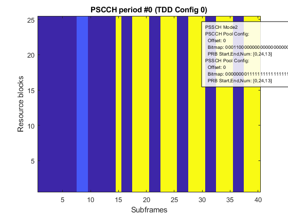
% period. The lighter blue part represents the PSCCH resource pool for SCI
% control information, and the yellow region is the PSSCH resource pool for
% PSSCH shared data
displayPeriod(period);
snapnow;

% Re-configure for TDD then display the updated properties and pool
% locations
period.Config.DuplexMode = 'TDD';
displayPeriod(period);
snapnow;

% The PSCCHPeriod class includes other default parameter structures that
% can be used to configure an object. These are based on a subset of the
% reference pool configurations of TS 36.101 Section A.7.2
configuration = PSCCHPeriod.defaultConfig(1,'5MHz')
period =

  PSCCHPeriod with properties:

            NSubframeBegin: 0
              PeriodLength: 40
                    TxMode: 'Mode2'
         PSCCHSubframePool: [3 4]
    PSCCHResourceBlockPool: [25×1 double]
          NumPSCCHResource: 24
         PSSCHSubframePool: [8 9 10 11 12 13 14 15 16 17 18 … ] (1×32 double)
    PSSCHResourceBlockPool: [25×1 double]
               AllowedITRP: [70×1 double]
             SyncSubframes: []
                    Config: [1×1 struct]

configuration =

  struct with fields:

                            NSLRB: 25
                       DuplexMode: 'FDD'
                        TDDConfig: 0
                       UESelected: 'On'
                       SyncEnable: 'On'
                     NPSCCHPeriod: 0
                    sc_CP_Len_r12: 'Normal'
                    sc_Period_r12: 40
         sc_TF_ResourceConfig_r12: [1×1 struct]
                  data_CP_Len_r12: 'Normal'
            dataHoppingConfig_r12: [1×1 struct]
    ue_SelectedResourceConfig_r12: [1×1 struct]
                       syncConfig: [1×1 struct]
PSCCH Subframe and Resource Block Pools
The PSCCH resource pool is parameterized by the sc-TF-ResourceConfig-r12 information element which is of type SL-TF-ResourceConfig-r12. This type is also used to define the PSSCH resource pool in the case of PSSCH transmission mode 2. The parameters in this IE determine both the PSCCH subframe and resource block pools. It contains the following parameters:
SL-TF-ResourceConfig-r12 ::= SEQUENCE {
prb-Num-r12 INTEGER (1..100),
prb-Start-r12 INTEGER (0..99),
prb-End-r12 INTEGER (0..99),
offsetIndicator-r12 SL-OffsetIndicator-r12,
subframeBitmap-r12 SubframeBitmapSL-r12
}
In the case of the PSCCH, the offsetIndicator-r12 parameter defines the offset of the PSCCH period sequence relative to SFN/DFN #0. The first subframe of the i-th PSCCH period is given by jbegin = offsetIndicator-r12 + i * sc-Period-r12. The subframeBitmap-r12 parameter is used to select subframes from the start of a period for the PSCCH subframe pool. The three parameters, prb-Num-r12, prb-Start-r12 and prb-End-r12 are used to select the PRB for the PSCCH resource block pool. Depending on the parameter values this pool can be formed from either one or two contiguous sets of resource blocks. This is described in more detail below.
% Display the parameter structure used to configure the PSCCH resource pools
period = PSCCHPeriod;
pscchpoolparams = period.Config.sc_TF_ResourceConfig_r12
pscchpoolparams =

  struct with fields:

            prb_Num_r12: 13
          prb_Start_r12: 0
            prb_End_r12: 24
    offsetIndicator_r12: 0
     subframeBitmap_r12: '0001100000000000000000000000000000000000'
The PSCCH subframe pool is defined by the subframeBitmap-r12 parameter which is part of the sc-TF-ResourceConfig-r12 information element. For the subframe pool the first  uplink subframes in the PSCCH period are selected where
  is the length of the bitmap. These subframes are denoted by their indices
  . The PSCCH subframe pool then comprises the uplink subframes associated with the 1's in the bitmap
  and the resulting pool is denoted by
  where
where  is the number of subframes in the pool.
% Display the PSCCH subframe pool bitmap parameter, subframeBitmap_r12
pscchsubframebitmap = period.Config.sc_TF_ResourceConfig_r12.subframeBitmap_r12
% Display the subframe pool indices (0-based, relative to the start of the
% PSCCH period) selected by the 1's in the bitmap
pscchsubframepool = period.PSCCHSubframePool

% Change the duplexing mode to TDD and observe the difference in subframe
% pool indices to account for the new uplink subframe positions for the
% current TDD configuration
period.Config.DuplexMode = 'TDD';
tddconfig = period.Config.TDDConfig
pscchsubframepool = period.PSCCHSubframePool
pscchsubframebitmap =

    '0001100000000000000000000000000000000000'


pscchsubframepool =

     3     4


tddconfig =

     0


pscchsubframepool =

     7     8
The PSCCH resource block pool is defined by the three parameters prb-Start-r12, prb-End-r12 and prb-Num-r12, which are also part of the sc-TF-ResourceConfig-r12 information element.
The parameters define two bands prb-Start-r12  (
(prb-Start-r12 + prb-Num-r12) and (prb-End-r12 - prb-Num-12) 
prb-End-r12. The resulting indices are denoted by  where
where  is the number of blocks in the resource pool. The bands can overlap to form a single contiguous block.
% Display the PSCCH resource block pool parameters, prb_Start-r12, prb-End-r12, prb-Num-r12
prbstart = period.Config.sc_TF_ResourceConfig_r12.prb_Start_r12
prbend = period.Config.sc_TF_ResourceConfig_r12.prb_End_r12
prbnum = period.Config.sc_TF_ResourceConfig_r12.prb_Num_r12

% Display the resource block pool indices (0-based) resulting from these
% parameters
pscchprbpool = period.PSCCHResourceBlockPool

% Change the prb-Num-r12 parameter and observe the difference in the
% resource block pool indices to account for the reduction in the size of
% the pool bands
prbnum = 2
period.Config.sc_TF_ResourceConfig_r12.prb_Num_r12 = prbnum;
pscchprbpool = period.PSCCHResourceBlockPool
prbstart =

     0


prbend =

    24


prbnum =

    13


pscchprbpool =

     0
     1
     2
     3
     4
     5
     6
     7
     8
     9
    10
    11
    12
    13
    14
    15
    16
    17
    18
    19
    20
    21
    22
    23
    24


prbnum =

     2


pscchprbpool =

     0
     1
    23
    24
The following demonstrates some of the effects of these parameters visually.
% Display the PSCCH pool resource locations for the default configuration.
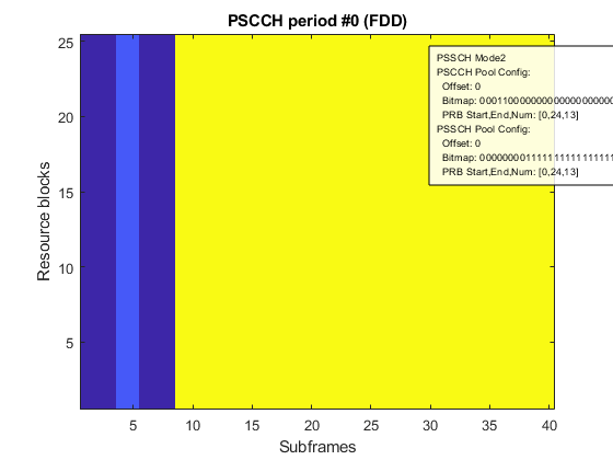
% For this parameterization the PSCCH resource block pool spans the entire
% bandwidth and the PSCCH subframe pool is a pair of contiguous subframes
% (the lighter blue area towards the start of the period)
period = PSCCHPeriod;
displayPeriod(period);
snapnow;

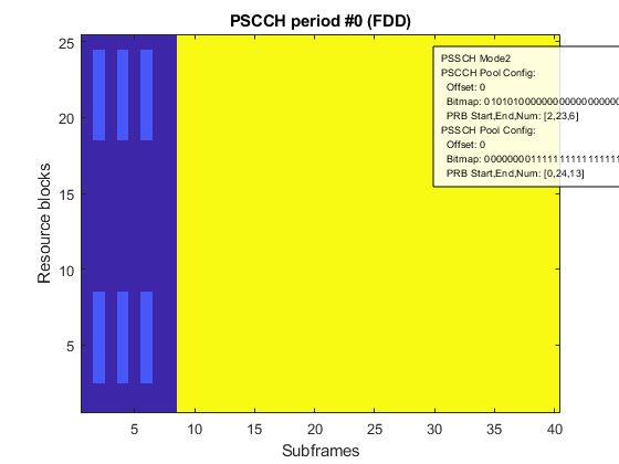
% Modify the subframe bitmap and resource block pool parameters to create
% non-contiguous pools
newconfig.prb_Num_r12 = 6;
newconfig.prb_Start_r12 = 2;
newconfig.prb_End_r12 = 23;
newconfig.offsetIndicator_r12 = 0;
newconfig.subframeBitmap_r12 = '0101010000000000000000000000000000000000';
period.Config.sc_TF_ResourceConfig_r12 = newconfig;
displayPeriod(period);
snapnow;
PSSCH Subframe and Resource Block Pools
The parameterization and structure of the PSSCH subframe and resource block pool depends on the transmission mode.
For transmission mode 1, the PSSCH subframe pool comprises all the remaining uplink subframes that start immediately after the last subframe of the PSCCH subframe pool,  . The PSSCH resource block pool comprises the full transmission bandwidth,
  .
.
For transmission mode 2, the RRC message uses a similar parameterization approach to that of the PSCCH. If the communication pool message contains a ue-SelectedResourceConfig-r12 element, then the UE is in transmission mode 2 and it will self-select its final transmission resources from the PSSCH resource pools. These pools are defined using another instance of the same SL-TF-ResourceConfig-r12 parameter set that is used to structure the PSCCH pools.
The ue-SelectedResourceConfig-r12 information element is given by,
ue-SelectedResourceConfig-r12 ::= SEQUENCE {
data-TF-ResourceConfig-r12 SL-TF-ResourceConfig-r12,
trpt-Subset-r12 SL-TRPT-Subset-r12 OPTIONAL -- Need OP
}
The additional trpt-Subset-r12 parameter is a small bitmap (3 to 5 bits) which is used to restrict the set of  (time resource pattern index) values selectable by the UE. This affects the total number of transmission subframes that the UE can select from the PSSCH subframe pool and therefore the maximum number of transport blocks that can be sent in a scheduled period.
For the PSSCH subframe pool, the subframeBitmap-r12 bitmap selects the pool subframes from the set of all uplink subframes that start at the subframe number given by offsetIndicator-r12 (relative to the start of the period) and continue to the end of the period. The subframeBitmap-r12 bitmap is repeated so that it is at least as long as the uplink subframe set and is used to select the final PSSCH subframe pool. The PSSCH resource block pool is defined in the same way as with the PSCCH using the three parameters, prb-Num-r12, prb-Start-r12 and prb-End-r12.
% Configure for transmission mode 1 (not UE selected).
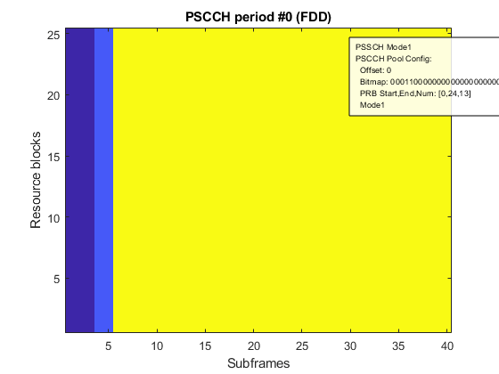
% Note that the PSSCH resource pool (yellow) is always full band and
% includes all uplink subframes in the period starting immediately after
% the PSCCH pool (lighter blue)
period = PSCCHPeriod;
period.Config.UESelected = 'off';
displayPeriod(period);
snapnow;

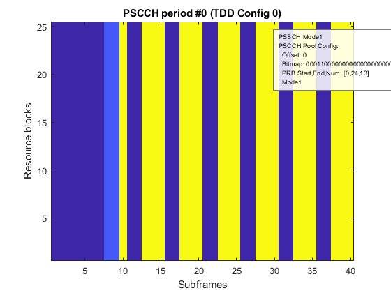
% Change to TDD and note the subframe gaps in the period due to the
% downlink subframes
period.Config.DuplexMode = 'TDD';
displayPeriod(period);
snapnow;

% Change back to transmission mode 2 (UE selected) and FDD.
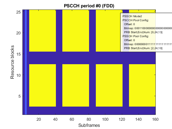
% Modify the PSSCH resource block pool parameters to create two distinct
% PRB bands
period.Config.UESelected = 'on';
period.Config.DuplexMode = 'FDD';
period.Config.ue_SelectedResourceConfig_r12.data_TF_ResourceConfig_r12.prb_Num_r12 = 10;
period.Config.ue_SelectedResourceConfig_r12.data_TF_ResourceConfig_r12.prb_Start_r12 = 2;
% Although the offset indicator is 0 relative to the start of the period,
% the leading 0's in the subframe bitmap create the gap between the period
% start and that of the PSSCH subframe pool
display(period.Config.ue_SelectedResourceConfig_r12.data_TF_ResourceConfig_r12);
displayPeriod(period);
snapnow;

% Increase the length of the period and note the gaps created in PSSCH
% subframe pool due to the repetition of the pattern of 0's in the
% configured subframe bitmap (40 bits) to cover the increased number of
% uplink subframes in the period.
period.Config.sc_Period_r12 = 160;  % 40,60,70,80,120,140,160,240,280,320 subframes, depending on duplexing config
displayPeriod(period);
snapnow;
  struct with fields:

            prb_Num_r12: 10
          prb_Start_r12: 2
            prb_End_r12: 24
    offsetIndicator_r12: 0
     subframeBitmap_r12: '0000000011111111111111111111111111111111'

Sidelink Transmission and Dynamic Resource Scheduling
As described above, when data is to be sent using a resource pool, the actual transmission resources are selected dynamically from within the pool using one of two different modes,
Transmission mode 1 - the serving eNodeB directs the resources via a DCI format 5 message sent to the transmitting UE
Transmission mode 2 - the transmitting UE self-selects the resources according to rules aimed at minimizing the collision risk
In both cases, the same physical layer parameters are used to manage the actual resource selection. The difference being that, for mode 1, these parameters are provided by the network whereas, for mode 2, they are chosen randomly by the UE (TS 36.321 Section 5.14.1.1 specifies - "randomly select the time and frequency resources for SL-SCH and SCI of a sidelink grant from the resource pool configured by upper layers. The random function shall be such that each of the allowed selections can be chosen with equal probability".)
The physical layer parameters are:
Resource for PSCCH value (
 ) - PSCCH subframes and resource blocks
Time Resource Pattern Index (
 ) - PSSCH subframes
Resource Allocation parameters (RIV, hopping bits) - PSSCH resource blocks
Resource Selection for PSCCH Transmission
The PSCCH control information associated with any PSSCH data transmission is sent twice on two separate PSCCH instances. Each PSCCH uses a different single PRB selected from the PSCCH resource block pool. The pair of subframes are selected from the PSCCH subframe pool. These PSCCH resources are signaled by a single scalar value  ("Resource for PSCCH"). The two subframe and PRB index pairs are derived according to TS 36.213 Sections 14.2.1.1 and 14.2.1.2. The range of allowed values is
  . The number of allowed values is given by the
 NumPSCCHResource property.
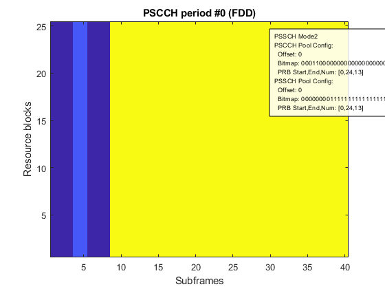
% Create an example PSCCH period and observe the location of the PSCCH
% subframe and resource block pools. Note that the PSCCH subframe pool
% contains only 2 entries in this case so all of the pool subframes will
% be used
period = PSCCHPeriod
displayPeriod(period);
snapnow;

% Select a valid nPSCCH value (use the last value in the allowed range)
% and return the associated PSCCH subframe and PRB indices
dci.PSCCHResource = period.NumPSCCHResource-1;
[subframes1,prb1,selected1] = period.getPSCCHResources(dci)

% Let the function select an nPSCCH value at random, as required by
% the collision avoidance mechanism used in transmission mode 2
sci.PSCCHResource = [];
[subframes2,prb2,selected2] = period.getPSCCHResources(sci)
period =

  PSCCHPeriod with properties:

            NSubframeBegin: 0
              PeriodLength: 40
                    TxMode: 'Mode2'
         PSCCHSubframePool: [3 4]
    PSCCHResourceBlockPool: [25×1 double]
          NumPSCCHResource: 24
         PSSCHSubframePool: [8 9 10 11 12 13 14 15 16 17 18 … ] (1×32 double)
    PSSCHResourceBlockPool: [25×1 double]
               AllowedITRP: [70×1 double]
             SyncSubframes: []
                    Config: [1×1 struct]
subframes1 =

     4     3


prb1 =

    11    23


selected1 =

    23


subframes2 =

     4     3


prb2 =

     9    21


selected2 =

    19
Similar to the use of the PDCCH and DCI in the downlink, the pair of PSCCH instances carry an SCI format 0 message which contains information used by the receiving UEs to decode the associated PSSCH sequence. There is no RNTI CRC masking in the SCI encoding. Instead the receiving UEs use the group destination ID contained within the SCI message payload to help filter out the PSSCH communications of interest (additional destination filtering is also done by higher layers).
SCI Format 0 message
Release 12 of the LTE standard specifies a single SCI format. For more information see lteSCI. The SCI format 0 is defined in TS 36.212 Section 5.4.3.1.1 by the following information fields:
- Frequency hopping flag - 1 bit as defined in TS 36.213 section 14.1.1
- Resource block assignment and hopping resource allocation -  bits
bits
-- For PSSCH hopping:
Hopping bits- MSB bits are used to obtain the value of
  as indicated in TS 36.213 section 8.4
RIV- bits provide the resource allocation in the subframe
-- For non-hopping PSSCH:
RIV- bits provide the resource allocation in the subframe as defined in TS 36.213 section 8.1.1
- Time resource pattern - 7 bits as defined in TS 36.213 section 14.1.1 ( )
)
- Modulation and coding scheme - 5 bits as defined in TS 36.213 section 14.1.1 ( )
)
- Timing advance indication - 11 bits as defined in TS 36.213 section 14.2.1
- Group destination ID - 8 bits as defined by higher layers ( )
)
% Display the SCI format 0 message field sizes for this example (5 MHz BW)
sci0 = lteSCI(period.Config,struct('SCIFormat','Format0','FreqHopping',1),'fieldsizes')
allocfields = sci0.Allocation

% Change BW to 10 MHz and notice the difference in resource field sizes
period.Config.NSLRB = 50;
sci0 = lteSCI(period.Config,struct('SCIFormat','Format0','FreqHopping',1),'fieldsizes')
allocfields = sci0.Allocation
sci0 =

  struct with fields:

              SCIFormat: 'Format0'
            FreqHopping: 1
             Allocation: [1×1 struct]
    TimeResourcePattern: 7
              ModCoding: 5
            TimeAdvance: 11
                  NSAID: 8
                Padding: 0


allocfields =

  struct with fields:

    HoppingBits: 1
            RIV: 8


sci0 =

  struct with fields:

              SCIFormat: 'Format0'
            FreqHopping: 1
             Allocation: [1×1 struct]
    TimeResourcePattern: 7
              ModCoding: 5
            TimeAdvance: 11
                  NSAID: 8
                Padding: 0


allocfields =

  struct with fields:

    HoppingBits: 2
            RIV: 9
Resource Selection for PSSCH Transmission
In the case of PSSCH, different parameters are used to specify the time and frequency resources. This differs from PSCCH, which signals the subframes and PRB to be used by a single value.
The subframes associated with the PSSCH transmission are indicated by the time resource pattern index,  . This index is used to look up a bitmap from a set of tables, with the choice of table being dependent on the duplexing configuration. The selected bitmap is denoted by
  where
where  is 6,7 or 8 depending on the table. This bitmap is repeated to form an extended bitmap
  which covers the entire PSSCH subframe pool. The subframes used for PSSCH transmission are selected by the 1 values in this extended bitmap to give the final subframe set denoted by
  where
where  is the number of subframes that can be used for PSSCH transmission in the PSCCH period and which will also be a multiple of 4. This aligns with the fact that each transport block transmitted within the period will be sent four times using the fixed HARQ RV sequence = 0,2,3,1. During a PSCCH period, as many of the scheduled quadruples are used as transport blocks that are available to send at that time.
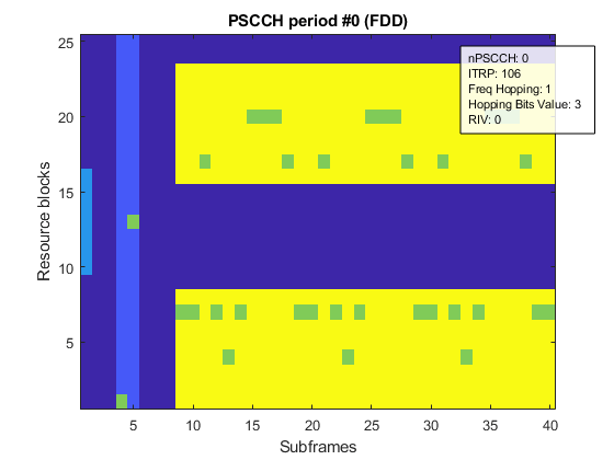
If frequency hopping is enabled, the resource blocks used in each of the transmission subframes depends on the RIV field and hopping bits. This is in addition to the semi-static dataHoppingConfig-r12 parameters and dependent resource block pool. The PRB will then depend on the position of the active subframe within the subframe pool.
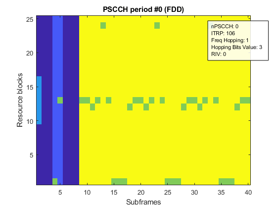
% Display the transmission resources used within the PSCCH/PSSCH resource
% pools. Turn PSSS/SSSS/PSBCH on for this example
period = PSCCHPeriod;
period.Config.SyncEnable = 'on';
period.Config.syncConfig.syncOffsetIndicator_r12 = 0;

% Define all the allocation control parameters, including an explicit PSCCH
% resource. Although in mode 2, this is effectively full DCI format 5
% parameterization, indicating SCI format 0 and PSCCH resource control
dci.PSCCHResource = 0;             % Select a specific PSCCH resource value
dci.TimeResourcePattern = 106;     % Select an unrestricted bitmap (all 1's)
dci.FreqHopping = 1;               % Configure frequency hopping with hopping type 2 (predefined sequence) and a single PRB allocation
dci.Allocation.HoppingBits = 3;    % Setting the value=3 will enable hopping type 2 for all BW (1 or 2 bits)

% Get the set of RIV that is associated with contiguous allocations within
% the current PSSCH resource pool. Set the first RIV which will be a single
% PRB allocation
[riv,range] = getAllowedRIV(period,dci);
dci.Allocation.RIV = riv(1);

% Display subframe indices and prb indices associated with the dynamic allocation
[subframes,prb,poolindices] = period.getPSSCHResources(dci)
% Display the transmission resources in addition to the pool positions
displayPeriod(period,dci);
snapnow;

% Display the RRC parameters that affect the PSSCH resource allocation and
% modify the RB offset to move the PRB allocation away from the PRB pool edges
period.Config.dataHoppingConfig_r12
period.Config.dataHoppingConfig_r12.numSubbands_r12 = 2;
period.Config.dataHoppingConfig_r12.rb_Offset_r12 = 4;
displayPeriod(period,dci);
snapnow;

% Display the UE selected (mode 2) PSCCH resource pool configuration then
% modify the PRB resource block pool parameters to created two distinct
% resource groups in the pool away from the band edges
dataresconfig = period.Config.ue_SelectedResourceConfig_r12.data_TF_ResourceConfig_r12
dataresconfig.prb_Start_r12 = 0;
dataresconfig.prb_End_r12 = 22;
dataresconfig.prb_Num_r12 = 8;
period.Config.ue_SelectedResourceConfig_r12.data_TF_ResourceConfig_r12 = dataresconfig;
% Display the updated resource pool and its effect on the transmission resources
displayPeriod(period,dci);
snapnow;

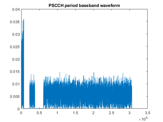
% Finally generate and plot the associated baseband waveform
figure
waveform = generateWaveform(period,dci);
plot(abs(waveform)); title('PSCCH period baseband waveform');
snapnow;
subframes =

  Columns 1 through 13

     8     9    10    11    12    13    14    15    16    17    18    19    20

  Columns 14 through 26

    21    22    23    24    25    26    27    28    29    30    31    32    33

  Columns 27 through 32

    34    35    36    37    38    39


prb =

  1×32 uint64 row vector

  Columns 1 through 15

   12   12   11   12   23   12    0    0    0   11   12   12   11   12   23

  Columns 16 through 30

   12    0    0    0   11   12   12   11   12   23   12    0    0    0   11

  Columns 31 through 32

   12   12


poolindices =

  Columns 1 through 13

     0     1     2     3     4     5     6     7     8     9    10    11    12

  Columns 14 through 26

    13    14    15    16    17    18    19    20    21    22    23    24    25

  Columns 27 through 32

    26    27    28    29    30    31
ans =

  struct with fields:

    hoppingParameter_r12: 504
         numSubbands_r12: 2
           rb_Offset_r12: 0

dataresconfig =

  struct with fields:

            prb_Num_r12: 13
          prb_Start_r12: 0
            prb_End_r12: 24
    offsetIndicator_r12: 0
     subframeBitmap_r12: '0000000011111111111111111111111111111111'
Appendix
This example uses this helper class.
Selected Bibliography
3GPP TS 36.101 "User Equipment (UE) radio transmission and reception"
3GPP TS 36.211 "Physical channels and modulation"
3GPP TS 36.212 "Multiplexing and channel coding"
3GPP TS 36.213 "Physical layer procedures"
3GPP TS 36.321 "Medium Access Control (MAC) protocol specification"
3GPP TS 36.331 "Radio Resource Control (RRC) protocol specification"