LTE Transmitter Using Software Defined Radio
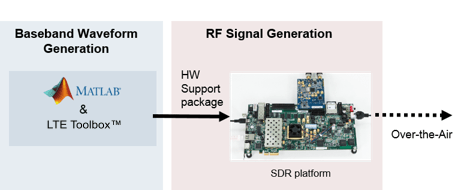
This example shows how to generate a reference measurement channel (RMC) downlink (DL) LTE waveform suitable for over-the-air transmission. This example also shows how to use a software-defined radio (SDR) to transmit the generated waveform using single or multiple antennas.
Introduction
This example generates eight frames of a baseband RMC DL waveform. Using SDR hardware such as the ADALM-Pluto Radio, this baseband waveform can be modulated for RF transmission. The SDR transmits the waveform by looping transmission of the eight frames for a specified time period.

Required Hardware and Software
By default, this example only generates an RMC DL waveform. Optionally, you can transmit the waveform over-the-air. For this, you need one of the following:
ADALM-PLUTO radio and Communications Toolbox Support Package for Analog Devices® ADALM-PLUTO Radio.
USRP™ E310/E312 and Communications Toolbox Support Package for USRP™ Embedded Series Radio.
USRP N2xx or B2xx series radio and Communications Toolbox Support Package for USRP Radio. For information on supported radios, see Supported Hardware and Required Software.
USRP E320, N3xx, X3xx, or X4xx series radio and Wireless Testbench Support Package for NI USRP Radios. For information on supported radios, see Supported Radio Devices (Wireless Testbench).
Example Setup
Before running the example, ensure that you have installed the appropriate support package for the SDR that you intend to use and that you have configured the hardware.
The TransmitOnSDR field of the txsim structure determines whether the example transmits the generated waveform using an SDR.
txsim.TransmitOnSDR =  false;
If you select the TransmitOnSDR field of the txsim structure, configure the variables required for SDR transmission.
if txsim.TransmitOnSDR txsim.SDRDeviceName ="Pluto"; % SDR that is used for waveform transmission txsim.RunTime =
20; % Time period to loop waveform in seconds txsim.RadioCenterFrequency =
2450000000; % Center frequency in Hz txsim.RadioIdentifier =
'usb:0'; % Value used to identify radio, for example, IP Address, USB Port, or Serial Number end
Configure the other fields in the txsim structure for LTE downlink waveform generation.
txsim.RC ="R.4"; % Base RMC configuration, 1.4 MHz bandwidth txsim.NCellID =
17; % Physical layer cell identity txsim.NFrame =
700; % Initial frame number txsim.TotFrames =
8; % Number of frames to generate txsim.NumAntennas =
1; % Number of transmit antennas
Transmitter Design
Follow these steps to understand how the LTE transmitter functions.
Generate a baseband LTE signal.
Prepare the baseband signal for transmission using the SDR hardware.
Send the baseband data to the SDR hardware for upsampling and transmission at the desired center frequency.
Generate Baseband LTE Signal
The lteRMCDLTool function provides the default configuration parameters defined in 3GPP TS 36.101 Annex A.3, which are required to generate an RMC.
Customize the parameters within the configuration structure rmc.
rmc = lteRMCDL(txsim.RC);
rmc.NCellID = txsim.NCellID;
rmc.NFrame = txsim.NFrame;
rmc.TotSubframes = txsim.TotFrames*10; % 10 subframes per frame
rmc.CellRefP = txsim.NumAntennas;      % Configure number of cell-specific reference signal antenna ports
rmc.OCNGPDSCHEnable = "On";            % Adds noise to unallocated PDSCH resource elements
If using two or more antennas, enable transmit diversity.
if rmc.CellRefP >= 2
    rmc.PDSCH.TxScheme = "TxDiversity";
    rmc.OCNGPDSCH.TxScheme = "TxDiversity";
else
    rmc.PDSCH.TxScheme = "Port0";
    rmc.OCNGPDSCH.TxScheme = "Port0";
end
rmc.PDSCH.NLayers = txsim.NumAntennas;
Create the baseband waveform (eNodeBOutput), a fully populated resource grid (txGrid), and the full configuration of the RMC using the lteRMCDLTool function.
trData = [1;0;0;1]; % Transport data
[eNodeBOutput,txGrid,rmc] = lteRMCDLTool(rmc,trData);
txsim.SamplingRate = rmc.SamplingRate;
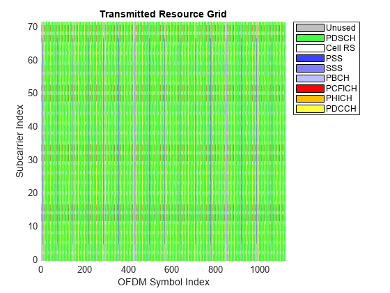
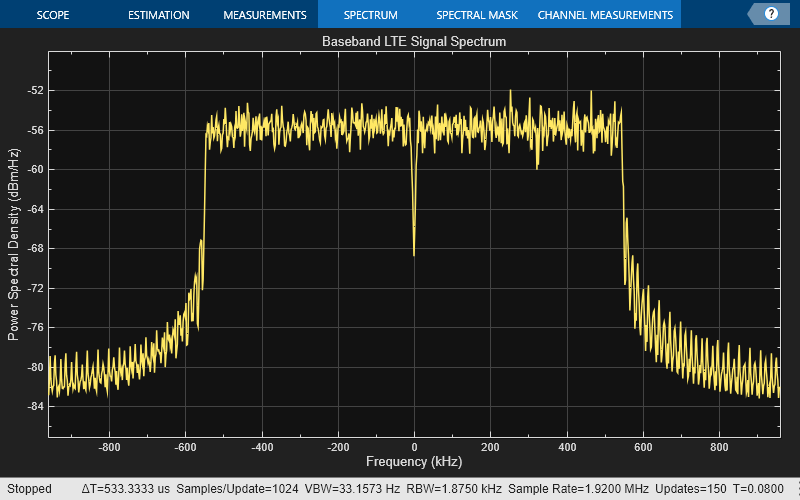
Display the resource grid populated with the highlighted channels and the power spectral density of the LTE baseband signal. You can see a 1.4 MHz signal bandwidth at baseband in the spectrum plot.
If using multiple transmit antennas, set displayAntennaForGrid to the antenna port you would like to display.
displayAntennaForGrid = 1;
ax = axes;
hPlotDLResourceGrid(rmc,txGrid(:,:,displayAntennaForGrid),ax,displayAntennaForGrid);
ax.Children(1).EdgeColor = "none";
title("Transmitted Resource Grid");

Display the power spectral density.
spectrumScope = spectrumAnalyzer( ...
    SampleRate=txsim.SamplingRate, ...
    SpectrumType="power-density", ...
    Title="Baseband LTE Signal Spectrum", ...
    YLabel="Power Spectral Density");
spectrumScope(eNodeBOutput);
release(spectrumScope);

Prepare for Transmission
The transmitter plays the LTE signal in a loop. The example splits the baseband signal into LTE frames of data, and the SDR Transmitter object (sdrTransmitter) transmits a full LTE frame. The example reshapes the baseband LTE signal into an - by - array, where is the number of samples per LTE frame and is the number of frames generated.
if txsim.TransmitOnSDR
    % Scale the signal for better power output and convert to int16, which
    % is the native format for the SDR hardware.
    powerScaleFactor = 0.7;
    eNodeBOutput = eNodeBOutput.*(1./max(abs(eNodeBOutput))*powerScaleFactor);
    eNodeBOutput = int16(eNodeBOutput*2^15);

    % LTE frames are 10 ms long
    samplesPerFrame = 10e-3*txsim.SamplingRate;
    numFrames = length(eNodeBOutput)/samplesPerFrame;

    % Ensure you are using an integer number of frames
    if mod(numFrames,1)
        warning("Non integer number of frames. Trimming transmission ...");
        numFrames = floor(numFrames);
    end

    % Reshape the baseband LTE data into frames for simpler transmission
    fprintf("Splitting transmission into %i frames\n",numFrames)
    txFrame = reshape(eNodeBOutput,samplesPerFrame,numFrames,txsim.NumAntennas);

    if matches(txsim.SDRDeviceName, ["Pluto", "E3xx"])
        sdrTransmitter = sdrtx( ...
            txsim.SDRDeviceName, ...
            CenterFrequency=txsim.RadioCenterFrequency, ...
            BasebandSampleRate=txsim.SamplingRate);
        if matches(txsim.SDRDeviceName, "E3xx")
            sdrTransmitter.ShowAdvancedProperties = true;
            sdrTransmitter.BypassUserLogic = true;
            sdrTransmitter.IPAddress = txsim.RadioIdentifier;
        else
            sdrTransmitter.RadioID = txsim.RadioIdentifier;
        end
    else
        % For the USRP SDRs
        sdrTransmitter = comm.SDRuTransmitter(...
            Platform=txsim.SDRDeviceName,...
            CenterFrequency=txsim.RadioCenterFrequency);
        [sdrTransmitter.MasterClockRate, sdrTransmitter.InterpolationFactor] = ...
            hGetUSRPRateInformation(txsim.SDRDeviceName,txsim.SamplingRate);
        if matches(txsim.SDRDeviceName, ["B200", "B210"])
            % Change the serial number as needed for USRP B200/B210
            sdrTransmitter.SerialNum = txsim.RadioIdentifier;
        else
            sdrTransmitter.IPAddress = txsim.RadioIdentifier;
        end
        sdrTransmitter.EnableBurstMode = true;
        sdrTransmitter.NumFramesInBurst = numFrames;
    end
    sdrTransmitter.ChannelMapping = 1:txsim.NumAntennas;
end
Transmission Using SDR Hardware
The example uses a try block to transfer the baseband data to the SDR hardware. Using the try, catch block means that if an error occurs during the transmission, the hardware releases the resources used by the SDR System object™. The sdrTransmitter System object transmits a full frame of LTE data.
if txsim.TransmitOnSDR
    fprintf("Starting transmission at Fs = %g MHz\n",txsim.SamplingRate/1e6)
    currentTime = 0;
    try
        while currentTime<txsim.RunTime
            for n = 1:numFrames
                bufferUnderflow = sdrTransmitter(squeeze(txFrame(:,n,:)));
                if bufferUnderflow
                    warning("Dropped samples.")
                end
            end
            currentTime = currentTime+numFrames*10e-3; % One frame is 10 ms
        end
    catch ME
        release(sdrTransmitter);
        rethrow(ME)
    end
    fprintf("Transmission finished\n")
    release(sdrTransmitter);
end
Further Exploration
You can use the companion example LTE Receiver Using Software-Defined Radio to decode the broadcast channel of the waveform generated by this example. Try changing the cell identity and initial system frame number and observe the detected cell identity and frame number at the receiver.
If using a supported multi-channel SDR, try increasing the number of antennas