NB-IoT Downlink Waveform Generation
This example shows how to generate LTE-Advanced Pro Release 13 narrowband IoT (NB-IoT) waveforms for test and measurement applications using LTE Toolbox™ software.
Introduction
3GPP introduced a new air interface, Narrowband IoT (NB-IoT) optimized for low data rate machine type communications in LTE-Advanced Pro Release 13. NB-IoT provides cost and power efficiency improvements as it avoids the need for complex signaling overhead required for LTE based systems.
The LTE Toolbox can be used to generate standard compliant NB-IoT downlink complex baseband waveforms representing the 180 kHz narrowband carrier suitable for test and measurement applications. The waveform consists of the individual physical layer channels and signals and the MATLAB value class NBIoTDownlinkWaveformGenerator can be used for full resource element (RE) grid and time-domain waveform generation. The LTE Toolbox supports all the NB-IoT modes of operation - standalone, guardband and in-band.
Standalone: NB-IoT carrier deployed outside the LTE spectrum, e.g. the spectrum used for GSM or satellite communications
Guardband: NB-IoT carrier deployed in the guardband between two LTE carriers
In-band: NB-IoT carrier deployed in resource blocks of a LTE carrier
In-band mode can be further grouped depending on the physical cell identity (PCI) used, Inband-SamePCI and Inband-DifferentPCI. If Inband-SamePCI, the physical layer cell identity and PCI are the same and the UE can make assumptions about the ports and channel from LTE signals. The operation mode is indicated in the NB-IoT MIB (MIB-NB), which provides essential information for the user equipment (UE). The network can use radio resource control information to allocate a non-anchor carrier to an UE operating in an anchor carrier, see TS 36.331 section 6.7.3.2 [ 5 ] and section 7.3.2.4 in [ 9 ].
This example creates the NB-IoT downlink, where the relevant physical layer channels and signals are:
Narrowband primary synchronization signal (NPSS)
Narrowband secondary synchronization signal (NSSS)
Narrowband reference signal (NRS)
Narrowband physical broadcast channel (NPBCH)
Narrowband physical downlink shared channel (NPDSCH)
Narrowband physical downlink control channel (NPDCCH)
NB-IoT supports two carrier configurations:
Anchor: The carrier used by the UE for initial NB-IoT cell selection, obtaining MIBs and system information blocks (SIBs), and random access in the idle mode. The NPSS, NSSS, NPBCH, and system information are transmitted on the carrier.
Non-anchor: A carrier only used for actual exchange of data in the connected mode. NPSS, NSSS, NPBCH, and system information are not transmitted on the carrier.
In this example, we demonstrate the NB-IoT downlink RE grid and waveform generation. The sections below explain the physical signals and channels that form the grid along with key concepts including subframe repetition, logical and transport channel mappings, and the corresponding grids for the different configurations. Moreover, the parameters involved in the waveform generation are shown to create waveforms as per user requirements.
The example outputs the complex baseband waveform along with the populated grid containing all the above mentioned physical channels and signals and also information about the type of data contained in each subframe. The waveform can be used for a range of applications from RF testing to simulation of receiver implementations.
NB-IoT Downlink Subframe Allocation
This section explains how the physical layer channels and signals mentioned above are mapped into the downlink subframes.
Downlink bit map: A logical vector to configure the NB-IoT downlink subframes. NB-IoT downlink subframes are defined as the subframes used for NPDCCH and NPDSCH not carrying SIB1-NB, it does not include subframes carrying NPSS, NSSS, NPBCH and NB-IoT system information block type 1 (SIB1-NB). The NB-IoT downlink subframes can be configured using parameter
Config.DownlinkBitmapin class NBIoTDownlinkWaveformGenerator.
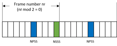
NPSS & NSSS: As illustrated in the figure below, the NPSS is transmitted in subframe 5 in every frame, and the NSSS is transmitted in subframe 9 in frames with frame number
nffulfillingnfmod 2 = 0. The NPSS and NSSS allow the UE to synchronize to the NB-IoT cell.
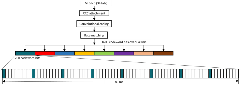
NPBCH: The NPBCH is used to carry the 34 bit MIB-NB (TS 36.212 section 6.4.1 [ 2 ]). The MIB-NB is coded to form a 1600 bits codeword (TS 36.211 section 10.2.4.1 [ 1 ]). The codeword is evenly segmented into 8 sub-blocks, each one has 200 bits which are transmitted on subframe 0 and repeated in the 7 following consecutive frames (TS 36.211 section 10.2.4.4 [ 1 ]). The mapping of the codeword bits is illustrated in the figure below.
NPDSCH: The key feature of NPDSCH is subframe repetition. NB-IoT defines two repetition schemes for the case when NPDSCH is carrying broadcast control channel (BCCH) or not. BCCH is the logical channel to carry SIB1-NB, system information messages, etc. Not carrying BCCH implies that NPDSCH may carry Paging Control Channel (PCCH), Common Control Channel (CCCH), Dedicated Control Channel (DCCH), Dedicated Traffic Channel (DTCH), etc (TS 36.300 sections 6.1.3.2 and 5.3.1a [ 6 ]). The two repetition schemes are illustrated in the figure below. The NPDSCH repetition parameters includes the number of subframes in a codeword
NSFand the number of repetitionsNRep. The example in the figure shows the repetition pattern withNRep= 4 for the case when NPDSCH is carrying BCCH andNRep= 8 for the case when NPDSCH is not carrying BCCH andNSF= 3 for both cases. For the case when carrying BCCH, all the subframes of a codeword are transmitted before repeating the codeword. For the case when not carrying BCCH, a subframe in the codeword is repeated bymin(NRep,4)before performing the same repetition for the other subframes. After the codeword is repeated bymin(NRep,4)times, the same procedure is performed until the full repetition is complete, i.e., repeated byNReptimes. The detailed specification of the repetition scheme can be found in TS 36.211 section 10.2.3 [ 1 ].

The repeated subframes shown in the above figure are mapped to the available subframes allocated for NPDSCH transmission. As a typical example, the following figure illustrates how to perform mapping for the subframes of NPDSCH carrying SIB1-NB, which contains the most important system information for an UE (TS 36.331 section 6.7.2 [ 5 ]).
A SIB1-NB is carried in 8 subframes (NSF = 8), and mapped to subframe 4 in every other frame in 16 continuous frames which are repeated NRep times (NRep = 4, 8 or 16, see TS 36.213 section 16.4.1.3 Table 16.4.1.3-3 [ 3 ]). The repetitions are equally spaced within a period of 256 frames (TS 36.331 section 5.2.1.2a [ 5 ]). The starting frame number for the first NPDSCH transmission in the period depends on the narrowband physical cell identity NNCellID as well as the number of repetitions NRep (TS 36.213 Table 16.4.1.3-4 [ 3 ]).

NB-IoT Downlink Grid
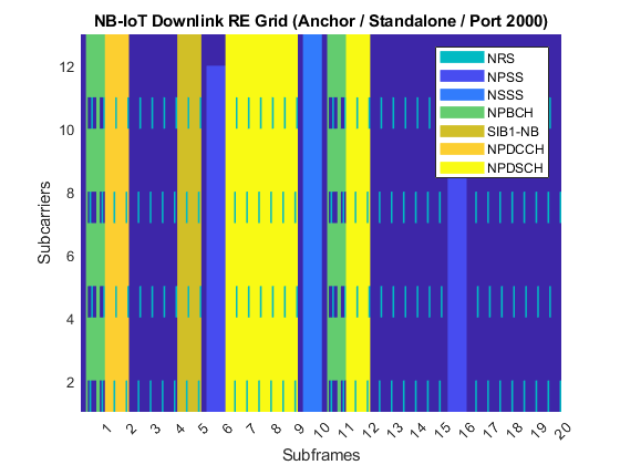
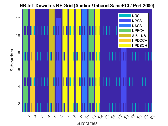
In addition to the subframe allocation described above, the generated grids below further explain the RE allocation in a subframe. The grid is for two frames of an anchor carrier containing NPSS, NSSS, NRS, NPBCH, SIB1-NB and NB-IoT downlink subframes carrying NPDSCH and NPDCCH. The grids are compared in Standalone and Inband-SamePCI operation modes. The grid can be generated using the grid display method in the class NBIoTDownlinkWaveformGenerator, i.e., creating an object ngen of type NBIoTDownlinkWaveformGenerator and calling ngen.displayResourceGrid.
NRS: The RE positions can be configured by the number of NRS ports and the narrowband physical cell identity, i.e., the parameter fields
NBRefPandNNCellIDin structurengen.Config, respectively.NPSS & NSSS: The first 11 subcarriers are used for NPSS, all 12 subcarriers in a physical resource block are used for NSSS. The first 3 OFDM symbols in a subframe are not used for NPSS/NSSS. NRS is not transmitted in any subframe containing NPSS/NSSS. The REs of NPSS/NSSS are punctured by the LTE cell-specific reference signal (CRS) only in in-band modes. The number of CRS ports that affects the puncturing can be configured by parameter field
CellRefPin structurengen.Config(TS 36.211 sections 10.2.6 and 10.2.7 [ 1 ]).NPBCH: The REs are punctured by the NRS and the CRS using the maximum number of NRS and CRS antenna ports (2 and 4, respectively), for both operation modes (TS 36.211 section 10.2.4 [ 1 ]). This is because the UE has no knowledge about the number of used antenna ports and the operation mode.
NPDSCH: For operation modes
StandaloneandGuardband, the REs are punctured by NRS only; for in-band operation modes, the REs are punctured by both NRS and CRS. When the operation mode is in-band, the first 3 OFDM symbols in the subframe are not used for NPDSCH carrying SIB1-NB, the firstControlRegionSizeOFDM symbols in the subframe are not used when NPDSCH is carried by a NB-IoT downlink subframe.ControlRegionSizeis a parameter field in structurengen.Configto configure the LTE control region size for NPDSCH RE allocations (TS 36.211 section 10.2.3.4 [ 1 ], TS 36.213 section 16.4.1.4 [ 3 ] and TS 36.331 section 6.7.2 [ 5 ]). The LTE control region size configures the starting OFDM symbol position in a NB-IoT downlink subframe carrying NPDSCH and NPDCCH in in-band operation modes.NPDCCH: The NRS and CRS puncturing are the same as that in NPDSCH described above. When the operation mode is in-band, the first
ControlRegionSizeOFDM symbols in the subframe are not used for NPDCCH. Same as that for NPDSCH,ControlRegionSizeis used to configure the NPDCCH RE allocations (TS 36.211 section 10.2.3.4 [ 1 ], TS 36.213 section 16.4.1.4 [ 3 ] and TS 36.331 section 6.7.2 [ 5 ]).
ngen = NBIoTDownlinkWaveformGenerator;

figure;
% Display the resource grid with default 'Standalone' operation mode
ngen.displayResourceGrid;
figure;
% Change the operation mode to 'Inband-SamePCI'
ngen.Config.OperationMode = 'Inband-SamePCI';
ngen.displayResourceGrid;
The object ngen contains the following:
Resource allocation and transport block size (TBS) tables for NPDSCH (see TS 36.213 sections 16.4.1.3 and 16.4.1.5 [ 3 ])
Structure
ngen.Configwith the NB-IoT eNodeB configuration where parameter fieldsNPBCH,SIB1NPDSCH,NPDCCHandNPDSCHconfigure NPBCH, NPDSCH carrying SIB1-NB, NPDCCH and NPDSCH not carrying SIB1-NB (i.e., NPDSCH carried by NB-IoT downlink subframes), respectively.
ngen                                      % Show all available properties
nsfTable = ngen.NSFTable                  % Display number of subframe table in TS 36.213 section 16.4.1.3
enbConfig = ngen.Config                   % Display NB-IoT eNodeB configuration
npbchConfig = ngen.Config.NPBCH           % Display NPBCH configuration
sib1npdschConfig = ngen.Config.SIB1NPDSCH % Display the configuration of NPDSCH when carrying SIB1-NB
ngen =

  NBIoTDownlinkWaveformGenerator with properties:

           Config: [1×1 struct]
         NSFTable: [8×2 table]
        NRepTable: [16×2 table]
         TBSTable: [176×3 table]
    NRepTableSIB1: [12×2 table]
     TBSTableSIB1: [12×2 table]


nsfTable =

  8×2 table

    ISF    NSF
    ___    ___

     0      1
     1      2
     2      3
     3      4
     4      5
     5      6
     6      8
     7     10


enbConfig =

  struct with fields:

          TotSubframes: 20
              NNCellID: 0
                NBRefP: 1
              CellRefP: 4
     ControlRegionSize: 3
                NFrame: 0
         OperationMode: 'Inband-SamePCI'
        DownlinkBitmap: [1 1 1 1 1 1 1 1 1 1]
           CarrierType: 'Anchor'
        DLGapThreshold: 32
      DLGapPeriodicity: 64
    DLGapDurationCoeff: 0.1250
             NPSSPower: 0
             NSSSPower: 0
                 NPBCH: [1×1 struct]
            SIB1NPDSCH: [1×1 struct]
                NPDCCH: [1×1 struct]
                NPDSCH: [1×1 struct]


npbchConfig =

  struct with fields:

           Power: 0
    EnableCoding: 'On'
     DataBlkSize: 34
      DataSource: 'PN9'


sib1npdschConfig =

  struct with fields:

          Enable: 'On'
           Power: 0
            NRep: 4
      Modulation: 'QPSK'
    EnableCoding: 'On'
     DataBlkSize: 208
      DataSource: 'PN9'
NPDCCH/NPDSCH Configuration
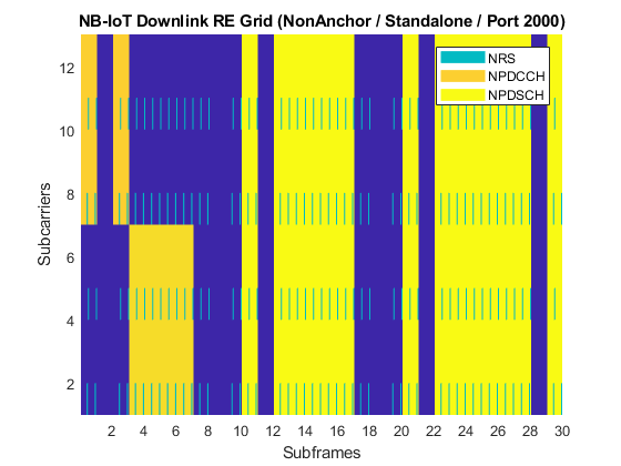
The generated RE grid below explains how to configure the subframes used for NB-IoT downlink subframes using downlink bit map, and how to configure the parameters of NPDCCH/NPDSCH carried by the NB-IoT downlink subframes. The NB-IoT downlink subframes can be configured by parameter field DownlinkBitmap in the structure ngen.Config. In the example, a non-anchor carrier is used to disable NPSS, NSSS, NPBCH and SIB1-NB in the grid.
The waveform generator supports multiple NPDCCH and NPDSCH. Each NPDSCH and NPDCCH contains a single transport block and downlink control information (DCI) message, respectively. The parameters of a NPDCCH/NPDSCH is specified by a structure, and multiple NPDCCH/NPDSCH are expressed as a structure vector.
A NPDCCH is configured by the following parameters in the structure ngen.Config.NPDCCH:
Enable: Enabling or disabling the NPDCCH ('On', 'Off').Power: Relative power for NPDCCH symbols in the frequency domain with assumption that the NRS power is 1.NCCE: The selected narrowband control channel elements (NCCEs) to carry the NDPCCH. The value can be either a scalar or a vector of two entries. A scalar or vector indicates NPDCCH format 0 or 1, respectively. Entry value 0 (or 1) indicates NCCE 0 (or NCCE 1). NCCE 0 occupies subcarriers 0 to 5 and NCCE 1 occupies subcarriers 6 to 11, respectively. (TS 36.211 section 10.2.5.1 [ 1 ]).NRep: Number of repetitions for a NPDCCH candidate (TS 36.213 section 16.6 [ 3 ]). Allowed values are , where n = 1...10.
Rmax: Maximum number of repetitions for NPDCCH (TS 36.213 section 16.6 [ 3 ]). It affects the NPDCCH transmission gap. Allowed values are , where n = 1...10.
RNTI: Radio network temporary identifier used for scrambling.StartSubframe: 0-based starting subframe index of the NPDCCH in the generated RE grid.DataBlkSize: Length of the DCI information bits.DataSource: DCI information bits. The parameter can be defined directly as a bit vector or using a random data type e.g., 'PN9-ITU', 'PN9', 'PN11', 'PN15', 'PN23'. For the latter case, a random bit vector is generated for the selected type.
A NPDSCH is configured by the following parameters in the structure ngen.Config.NPDSCH:
Enable: Enabling or disabling the NPDSCH ('On', 'Off').Power: Relative power for NPDSCH symbols in the frequency domain with assumption that the NRS power is 1.NPDSCHDataType: Type of data the NPDSCH carries, the allowed values are either 'BCCHNotSIB1NB' or 'NotBCCH'. This value affects the repetition scheme as described above.NRep: The number of repetitions (TS 36.211 section 16.4.1.3 [ 1 ]).NSF: The number of subframes in a NPDSCH codeword (TS 36.211 section 16.4.1.3 [ 1 ]).Rmax: Maximum number of repetitions for the NPDCCH associated to the NPDSCH, its value should be equal to the value of the same field in the corresponding NPDCCH.StartSubframe: 0-based starting subframe index of the NPDSCH in the generated RE grid.Modulation: Modulation used by the NPDSCH ('QPSK','16QAM').DataBlkSize: Transport block size.DataSource: Information bits of the transport block. The usage is the same as the same field in structurengen.Config.NPDCCH.
ngen = NBIoTDownlinkWaveformGenerator;
ngen.Config.CarrierType = 'NonAnchor'; % Anchor or NonAnchor
ngen.Config.DownlinkBitmap = [1 0 1 1 1 1 1 1 0 1];
ngen.Config.TotSubframes = 30;

% Configure the parameters of the first NPDCCH
npdcch1.Enable = 'On';
npdcch1.Power = 0;
npdcch1.NCCE = 1;  % NPDCCH format 0 with NCCE 1
npdcch1.NRep = 2;
npdcch1.Rmax = 16;
npdcch1.RNTI = 0;
npdcch1.StartSubframe = 0;
npdcch1.DataBlkSize = 23;
npdcch1.DataSource = randi([0 1],npdcch1.DataBlkSize,1); % Users can define their own information bits

% Configure the parameters of the second NPDCCH
npdcch2.Enable = 'On';
npdcch2.Power = 0;
npdcch2.NCCE = 0;  % NPDCCH format 0 with NCCE 0
npdcch2.NRep = 4;
npdcch2.Rmax = 16;
npdcch2.RNTI = 1;
npdcch2.StartSubframe = 3;
npdcch2.DataBlkSize = 23;
npdcch2.DataSource = 'PN9';

% Configure the parameters of the first NPDSCH
npdsch1.Enable = 'On';
npdsch1.Power = 0;
npdsch1.NPDSCHDataType = 'BCCHNotSIB1NB';
npdsch1.NSF = 3;
npdsch1.NRep = 2;
npdsch1.Rmax = npdcch1.Rmax;
npdsch1.RNTI = 0;
npdsch1.StartSubframe = 10;
npdsch1.Modulation = 'QPSK';
npdsch1.DataBlkSize = 616;
npdsch1.DataSource = 'PN15';

% Configure the parameters of the second NPDSCH
npdsch2.Enable = 'On';
npdsch2.Power = 0;
npdsch2.NPDSCHDataType = 'NotBCCH';
npdsch2.NSF = 2;
npdsch2.NRep = 4;
npdsch2.Rmax = npdcch2.Rmax;
npdsch2.RNTI = 1;
npdsch2.StartSubframe = 20;
npdsch2.Modulation = 'QPSK';
npdsch2.DataBlkSize = 616;
npdsch2.DataSource = 'PN23';

% Prepare NPDSCH and NPDCCH structure vectors
ngen.Config.NPDCCH = [npdcch1 npdcch2];
ngen.Config.NPDSCH = [npdsch1 npdsch2];

figure;
ngen.displayResourceGrid;
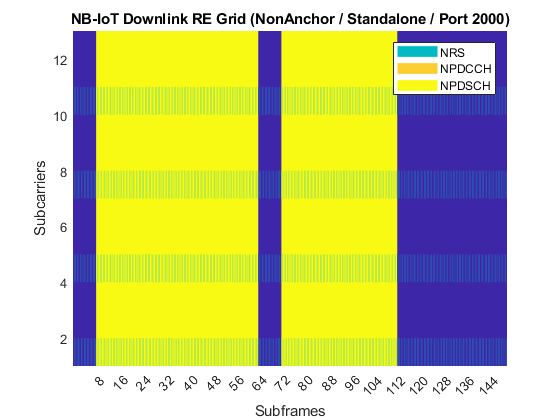
The generated RE grid below explains how to configure the transmission gap for NPDSCH/NPDCCH according to TS 36.211 sections 10.2.3.4 and 10.2.5.5 [ 1 ]. The gap is defined by parameter field Rmax mentioned above, as well as the following parameters in structure ngen.Config:
DLGapThreshold: Threshold to trigger the transmission gap, i.e., there are no gaps in the NPDSCH transmission ifRmax< |DLGapThreshold|. Allowed values are 32, 64, 128, 256 (TS 36.331 section 6.7.1 [ 5 ]).DLGapPeriodicity: The gap periodicity in number of subframes. It also defines the starting subframe of the gap, i.e., the starting subframe numbersfsatisfying condition (sf modDLGapPeriodicity) = 0. Allowed values are 64, 128, 256, 512 (TS 36.331 section 6.7.1 [ 5 ]).DLGapDurationCoeff: Used to calculate the gap duration in number of subframes, together withDLGapPeriodicity. The gap duration is given byDLGapPeriodicity
DLGapDurationCoeff. Allowed values are 1/8, 1/4, 3/8, 1/2 (TS 36.331 section 6.7.1 [ 5 ]).
The following example uses defaulting parameters DLGapThreshold = 32, DLGapPeriodicity = 64 and DLGapDurationCoeff = 1/8 to explain the NPDSCH transmission gap. The figure below illustrates that the 96 (NRep 
NSF) NPDSCH subframes is disrupted by two gaps with a duration of 8 subframes, and the two gaps start at subframe 0 and subframe 64, respectively.
ngen = NBIoTDownlinkWaveformGenerator;
ngen.Config.CarrierType = 'NonAnchor'; % Anchor or NonAnchor
ngen.Config.TotSubframes = 150;
ngen.Config.NPDCCH.Enable = 'Off';     % Disable the NPDCCH
ngen.Config.NPDSCH.StartSubframe = 0;
ngen.Config.NPDSCH.Rmax = ngen.Config.DLGapThreshold; % Minimum value to trigger the transmission gap based on given DLGapThreshold
ngen.Config.NPDSCH.NRep = 32;
ngen.Config.NPDSCH.NSF = 3;

figure;
ngen.displayResourceGrid;
NB-IoT Downlink Waveform Generation
Generate the time-domain waveform of a reference measurement channel (RMC) for NPDSCH performance requirements, according to TS 36.101 Appendix A.3.12 [ 7 ], or the NB Test Model (N-TM), defined in TS 36.141 sections 6.1.3-6.1.6 [ 8 ]. The waveform can be generated using the waveform generation method in the class NBIoTDownlinkWaveformGenerator, to call the method, an object ngen is created and the method can be called by using ngen.generateWaveform.
rc = 'R.NB.5-1'; % Allowed values are 'R.NB.5','R.NB.5-1','R.NB.6','R.NB.6-1','R.NB.7','R.NB.8','R.NB.9','N-TM'
ngen = NBIoTDownlinkWaveformGenerator(rc);
[waveform,grid,ofdmInfo] = ngen.generateWaveform;
ofdmInfo         % Display OFDM configuration
spectrumScope = spectrumAnalyzer;
spectrumScope.SampleRate = ofdmInfo.SamplingRate;
spectrumScope.ShowLegend = true;
if ngen.Config.NBRefP == 1
    spectrumScope.ChannelNames = {['Signal for RMC ' rc ' (Port 2000)']};
    spectrumScope(waveform);
else % NBRefP == 2
    spectrumScope.ChannelNames = {['Signal for RMC ' rc ' (Port 2000)'], ...
        ['Signal for RMC ' rc ' (Port 2001)']};
    spectrumScope(waveform(:,1),waveform(:,2));
end
ofdmInfo =

  struct with fields:

            SamplingRate: 1920000
                    Nfft: 128
               Windowing: 6
     CyclicPrefixLengths: [10 9 9 9 9 9 9 10 9 9 9 9 9 9]
    SubframeChannelTypes: ["NPDCCH"    "Unused"    …    ] (1×20 string)
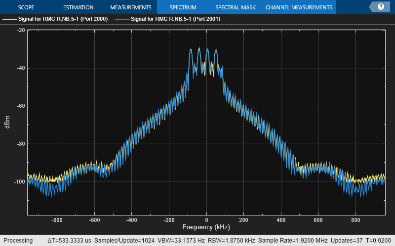
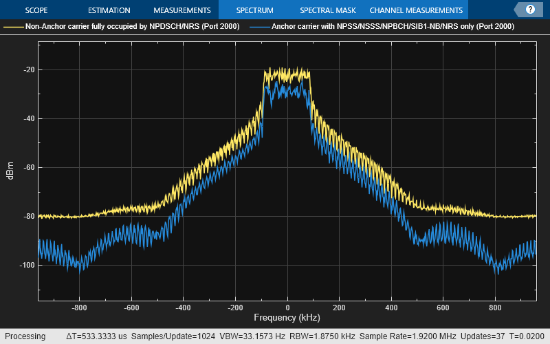
The following figures compare the signal spectrums for the generated time-domain waveform. As shown in the spectrum analyzer, the signal with yellow color has stronger power than the one with blue color. This is because the RE usage percentage of yellow one is higher.
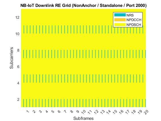
% Set up a standalone, non-anchor carrier, disable the NPDCCH and make the
% REs grid fully occupied by NPDSCH/NRS.
ngen = NBIoTDownlinkWaveformGenerator;
ngen.Config.CarrierType = 'NonAnchor';
ngen.Config.NPDCCH.Enable = 'Off'; % Disable the NPDCCH
ngen.Config.NPDSCH.StartSubframe = 0;
ngen.Config.NPDSCH.NRep = 8;
ngen.Config.NPDSCH.NSF = 5;

% Display the grid and generate the time-domain signal
figure;
ngen.displayResourceGrid;
[waveform1,~,ofdmInfo1] = ngen.generateWaveform;

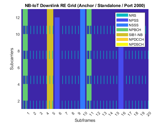
% Set up a standalone, anchor carrier, disable the NPDSCH and NPDCCH so
% that it contains NPSS/NSSS/NPBCH/SIB1-NB/NRS only.
ngen = NBIoTDownlinkWaveformGenerator;
ngen.Config.NPDCCH.Enable = 'Off'; % Disable the NPDCCH
ngen.Config.NPDSCH.Enable = 'Off'; % Disable the NPDSCH

% Display the grid and generate the time-domain signal
figure;
ngen.displayResourceGrid;
waveform2 = ngen.generateWaveform;

% Plot the signal spectrums of the generated two waveforms.
release(spectrumScope);
spectrumScope.ShowLegend = true;
spectrumScope.ChannelNames = {'Non-Anchor carrier fully occupied by NPDSCH/NRS (Port 2000)', ...
    'Anchor carrier with NPSS/NSSS/NPBCH/SIB1-NB/NRS only (Port 2000)'};
spectrumScope.SampleRate = ofdmInfo1.SamplingRate;
spectrumScope(waveform1,waveform2);
Selected Bibliography
3GPP TS 36.211 "Physical channels and modulation"
3GPP TS 36.212 "Multiplexing and channel coding"
3GPP TS 36.213 "Physical layer procedures"
3GPP TS 36.321 "Medium Access Control (MAC); Protocol specification"
3GPP TS 36.331 "Radio Resource Control (RRC); Protocol specification"
3GPP TS 36.300 "Overall description; Stage 2"
3GPP TS 36.101 "User Equipment (UE) radio transmission and reception"
3GPP TS 36.141 "Base Station (BS) conformance testing"
O. Liberg, M. Sundberg, Y.-P. Wang, J. Bergman and J. Sachs, Cellular Internet of Things: Technologies, Standards and Performance, Elsevier, 2018.