PDSCH Error Vector Magnitude (EVM) Measurement
This example measures the EVM within a downlink reference measurement channel (RMC) signal and a downlink test model (E-TM) signal, according to the EVM measurement requirements specified in TS 36.104, Annex E [ 1 ].
Introduction
This example creates an RMC signal and applies noise to the transmission to model transmitter EVM. Frequency offset and IQ offset are also applied. The impaired signal is then processed according to the EVM measurement requirements specified in TS 36.104, Annex E [ 1 ]. This example measures peak and RMS EVM averaged across the two frames of the input signal.
The average EVM is measured at two locations in time (low and high), where the low and high locations correspond to the alignment of the FFT window within the start and end of the cyclic prefix. LTE Toolbox™ requires the low and high locations to be specified as a fraction of the cyclic prefix length.
Note that for multi-antenna RMCs, the EVM measurement assumes each receive signal antenna is directly connected to each transmit signal antenna, as shown in TS36.141 Annex I.1.1 [ 2 ]. In accordance with the EVM measurement requirements defined in TS 36.104 Annex E [ 1 ], the PDSCH decoding uses only zero forcing equalization. For an illustration of PDSCH reception that includes complete MIMO decoding, see the Cell Search, MIB and SIB1 Recovery example.
Finally the EVM of a Test Model (E-TM) signal is measured, showing how to synchronize an E-TM signal that has been generated outside of MATLAB® or that has been played over-the-air after being generated inside MATLAB.
Transmitter
Setup the transmitter as per TS36.101 RMC [ 3 ].
% eNodeB Configuration
rng('default');         % Set the default random number generator
rmc = lteRMCDL('R.5');  % Configure RMC
rmc.PDSCH.RVSeq = 0;    % Redundancy version indicator
rmc.TotSubframes = 20;  % Total number of subframes to generate

% Create eNodeB transmission with random PDSCH data
txWaveform = lteRMCDLTool(rmc,randi([0 1],rmc.PDSCH.TrBlkSizes(1),1));
Impairment Modeling
Model the transmitter EVM and add frequency and IQ offsets.
% Model EVM with additive noise
ofdmInfo   = lteOFDMInfo(rmc);
txEVMpc    = 1.2;          % Transmit EVM in per cent
evmModel   = txEVMpc/(100*sqrt(double(ofdmInfo.Nfft)))* ...
    complex(randn(size(txWaveform)),randn(size(txWaveform)))/sqrt(2);
rxWaveform = txWaveform+evmModel;

% Add frequency offset impairment to received waveform
foffset    = 33.0;         % Frequency offset in Hertz
t = (0:length(rxWaveform)-1).'/ofdmInfo.SamplingRate;
rxWaveform = rxWaveform.*repmat(exp(1i*2*pi*foffset*t),1,rmc.CellRefP);

% Add IQ offset
iqoffset   = complex(0.01,-0.005);
rxWaveform = rxWaveform+iqoffset;
Receiver
The receiver synchronizes with the received signal and computes and displays the measured EVM.
% Apply frequency estimation and correction for the purposes of performing
% timing synchronization
foffset_est = lteFrequencyOffset(rmc,rxWaveform);
rxWaveformFreqCorrected = lteFrequencyCorrect(rmc,rxWaveform,foffset_est);

% Synchronize to received waveform
offset = lteDLFrameOffset(rmc,rxWaveformFreqCorrected,'TestEVM');
rxWaveform = rxWaveform(1+offset:end,:);

% Use 'TestEVM' pilot averaging
cec.PilotAverage = 'TestEVM';
Perform Measurements
The PDSCH EVM is calculated by calling hPDSCHEVM.
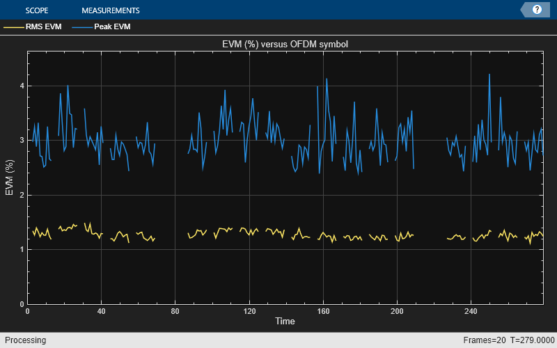
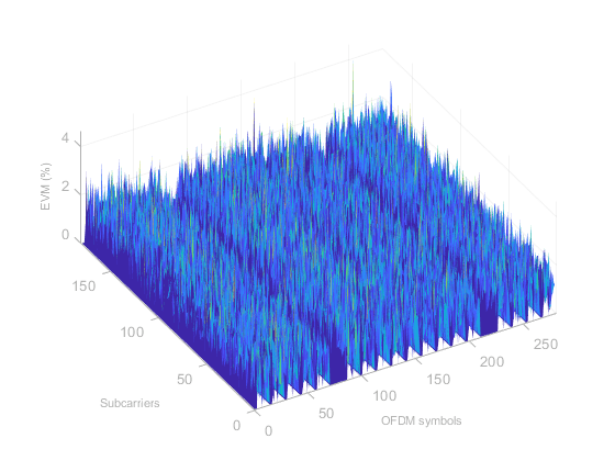
The average EVM for a downlink RMC is displayed. First the results for low and high edge EVM are calculated for each subframe within a frame and their averages are displayed at the command window. The max of these averages is the EVM per frame. The final EVM for the downlink RMC is the average of the EVM across all frames. A number of plots are also produced:
EVM versus OFDM symbol
EVM versus subcarrier
EVM versus resource block
EVM versus OFDM symbol and subcarrier (i.e. the EVM resource grid)
Note that the EVM measurement displayed at the command window is only calculated across allocated PDSCH resource blocks, in accordance with the LTE standard. The EVM plots are shown across all resource blocks (allocated or unallocated), allowing the quality of the signal to be measured more generally. In unallocated resource blocks, the EVM is calculated assuming that the received resource elements have an expected value of zero.
The EVM of each E-UTRA carrier for QPSK, 16QAM, 64QAM and 256QAM modulation schemes on PDSCH should be better than the required EVM of 17.5%, 12.5%, 8% and 3.5% respectively as per TS 36.104 Table 6.5.2-1 [ 1 ].
% Compute and display EVM measurements
[evmmeas, plots] = hPDSCHEVM(rmc,cec,rxWaveform);
Low edge EVM, subframe 0: 1.287%
High edge EVM, subframe 0: 1.289%
Low edge EVM, subframe 1: 1.395%
High edge EVM, subframe 1: 1.390%
Low edge EVM, subframe 2: 1.329%
High edge EVM, subframe 2: 1.324%
Low edge EVM, subframe 3: 1.234%
High edge EVM, subframe 3: 1.239%
Low edge EVM, subframe 4: 1.236%
High edge EVM, subframe 4: 1.229%
Low edge EVM, subframe 6: 1.295%
High edge EVM, subframe 6: 1.294%
Low edge EVM, subframe 7: 1.348%
High edge EVM, subframe 7: 1.344%
Low edge EVM, subframe 8: 1.339%
High edge EVM, subframe 8: 1.336%
Low edge EVM, subframe 9: 1.331%
High edge EVM, subframe 9: 1.319%
Averaged low edge EVM, frame 0: 1.312%
Averaged high edge EVM, frame 0: 1.308%
Averaged EVM frame 0: 1.312%
Low edge EVM, subframe 0: 1.243%
High edge EVM, subframe 0: 1.243%
Low edge EVM, subframe 1: 1.229%
High edge EVM, subframe 1: 1.229%
Low edge EVM, subframe 2: 1.217%
High edge EVM, subframe 2: 1.220%
Low edge EVM, subframe 3: 1.217%
High edge EVM, subframe 3: 1.220%
Low edge EVM, subframe 4: 1.239%
High edge EVM, subframe 4: 1.239%
Low edge EVM, subframe 6: 1.219%
High edge EVM, subframe 6: 1.207%
Low edge EVM, subframe 7: 1.243%
High edge EVM, subframe 7: 1.246%
Low edge EVM, subframe 8: 1.255%
High edge EVM, subframe 8: 1.252%
Low edge EVM, subframe 9: 1.249%
High edge EVM, subframe 9: 1.246%
Averaged low edge EVM, frame 1: 1.234%
Averaged high edge EVM, frame 1: 1.234%
Averaged EVM frame 1: 1.234%
Averaged overall EVM: 1.274%


EVM Measurement on a Test Model Signal
Finally the EVM of a Test Model (E-TM) signal is measured, showing how to synchronize an E-TM signal that has been generated outside of MATLAB or that has been played over-the-air after being generated inside MATLAB. The following steps are performed:
Load captured waveform: A waveform is generated inside
hGetTestModelWaveformto simulate an over-the-air E-TM waveform captured at the returned sample rate. For more details on over-the-air transmission and analysis of Test Model waveforms, refer to the following example: Waveform Generation and Transmission Using LTE Toolbox with Test and Measurement Equipment.Create local Test Model configuration: Next a configuration structure representing the E-TM waveform content is created using the function
lteTestModel. In order to create the configuration, the Test Model number and bandwidth must be known.Resample to expected sampling rate: The function
lteOFDMInfois called to get some information about the OFDM modulation/demodulation used within LTE Toolbox for the Test Model configurationtmconfig. The most important information here isofdmInfo.SamplingRatewhich gives the sampling rate expected for OFDM demodulation of the waveform. Theresamplefunction is used to resample the captured waveform to this sampling rate.Perform synchronization: Frequency offset estimation and correction and timing synchronization are performed using the same steps as shown earlier in this example.
Measure EVM: The EVM is measured by calling
hPDSCHEVM. For E-TMs, the generated waveform contains one or more PDSCHs. ThehPDSCHEVMfunction determines which PDSCH to analyze based on TS 36.141, section 6.1.1 [ 2 ].
% Load the captured Test Model waveform
[tmsignal,SR] = hGetTestModelWaveform();

% Create a local Test Model configuration, corresponding to the known E-TM
% number and bandwidth
tmconfig = lteTestModel('1.1','5MHz');
ofdmInfo = lteOFDMInfo(tmconfig);

% Resample the captured waveform to match the expected sampling rate used
% by LTE Toolbox for the Test Model bandwidth
tmsignal = resample(tmsignal,ofdmInfo.SamplingRate,SR);

% Apply frequency estimation and correction for the purposes of performing
% timing synchronization
foffset_est = lteFrequencyOffset(tmconfig,tmsignal);
tmsignalFreqCorrected = lteFrequencyCorrect(tmconfig,tmsignal,foffset_est);

% Synchronize the captured waveform
offset = lteDLFrameOffset(tmconfig,tmsignalFreqCorrected,'TestEVM');
tmsignal = tmsignal(1+offset:end,:);

% Compute EVM measurements, with plotting disabled
cec.PilotAverage = 'TestEVM';
alg.EnablePlotting = 'Off';
evm_tm = hPDSCHEVM(tmconfig,cec,tmsignal,alg);
Low edge EVM, subframe 0: 1.909%
High edge EVM, subframe 0: 1.922%
Low edge EVM, subframe 1: 1.895%
High edge EVM, subframe 1: 1.904%
Low edge EVM, subframe 2: 1.899%
High edge EVM, subframe 2: 1.915%
Low edge EVM, subframe 3: 1.897%
High edge EVM, subframe 3: 1.910%
Low edge EVM, subframe 4: 1.900%
High edge EVM, subframe 4: 1.920%
Low edge EVM, subframe 5: 1.901%
High edge EVM, subframe 5: 1.913%
Low edge EVM, subframe 6: 1.897%
High edge EVM, subframe 6: 1.912%
Low edge EVM, subframe 7: 1.900%
High edge EVM, subframe 7: 1.920%
Low edge EVM, subframe 8: 1.895%
High edge EVM, subframe 8: 1.905%
Low edge EVM, subframe 9: 1.895%
High edge EVM, subframe 9: 1.905%
Averaged low edge EVM, frame 0: 1.899%
Averaged high edge EVM, frame 0: 1.912%
Averaged EVM frame 0: 1.912%
Averaged overall EVM: 1.912%
Appendix
This example uses the following helper functions:
Selected Bibliography
3GPP TS 36.104 "Base Station (BS) radio transmission and reception"
3GPP TS 36.141 "Base Station (BS) conformance testing"
3GPP TS 36.101 "User Equipment (UE) radio transmission and reception"