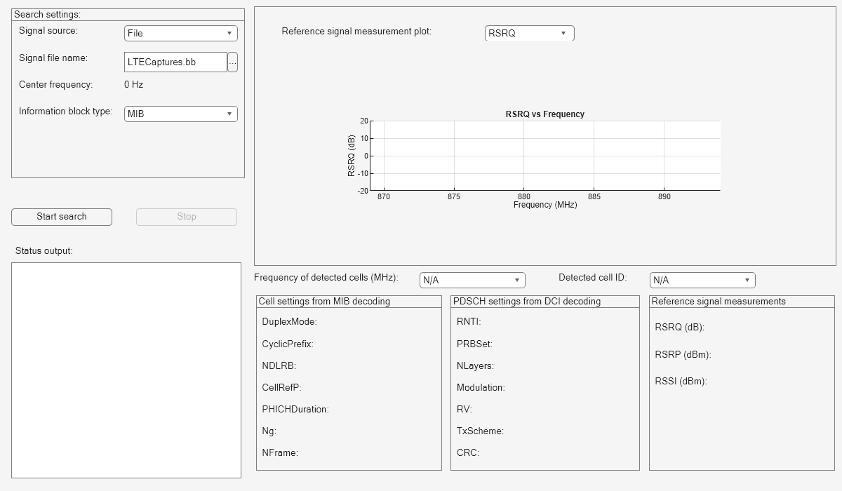
Scan and Decode LTE Waveform
This example shows how to capture and decode an LTE signal obtained either from a file or from radio by using LTE Toolbox™ software and various hardware support packages (HSPs). Before the user equipment (UE) can communicate with the network, it must perform cell search and selection procedures, and then obtain initial system information. This process involves acquiring slot and frame synchronization, determining the cell identity, and decoding the MIB and system information blocks (SIBs). This example launches a graphical user interface (GUI), which enables you to:
Provide all the inputs for scanning LTE waveforms
Capture live LTE waveforms using different radios
Analyze decoded MIB and SIB1 information
Visualize the reference signal measurements
Required Hardware and Software
To run this example using captured signals from a file, you need this file:
Baseband file (*.bb): Uses the comm.BasebandFileReader object to read previously captured LTE signals.
To receive signals in real time, you also need one of these software-defined radio (SDR) devices and the corresponding SDR support package add-on:
RTL-SDR Radio and Communications Toolbox Support Package for RTL-SDR.
ADALM-Pluto Radio and Communications Toolbox Support Package for Analog Devices® ADALM-Pluto Radio.
200-series USRP Radio and Communications Toolbox Support Package for USRP™ Radio.
300-series USRP Radio and Wireless Testbench and Wireless Testbench Support Package for NI™ USRP Radios. For more information, see Supported Radio Devices (Wireless Testbench).
AD936x/FMCOMMS5 and SoC Blockset and SoC Blockset™ Support Package for AMD® FPGA and SoC Devices. For more information, see AMD FPGA and SoC Devices (SoC Blockset).
For a full list of Communications Toolbox supported SDR platforms, refer to the Supported Hardware section of Software Defined Radio (SDR) discovery page.
Main GUI Call
This code launches the GUI, which you can use to capture and decode an LTE waveform.
hScanLTEWaveformGUI;

User Inputs
These search settings need to be provided through the GUI to perform the LTE scanning operation:
Signal source: Signal source can be any one of these options. By default the 'Signal source' is set to 'File'.
File: Over-the-air signals written to a baseband file (*.bb).
RTL-SDR: RTL-SDR radio.
ADALM-PLUTO: ADALM-PLUTO radio.
USRP-B200/B210: USRP® B series (either B200 or B210) radio.
USRP-N200/N210: USRP® N series (either N200 or N210) radio.
USRP-X300/X310: USRP® X series (either X300 or X310) radio.
ZedBoard-FMC2/3/4: Zynq® Evaluation and Development Board (ZedBoard) with FMC 2/3/4.
ZC706-FMC2/3/4: Zynq®-7000 SoC ZC706 Evaluation Kit with FMC 2/3/4.
All of these radios are used to capture the live LTE waveforms for the specific radio settings.
Signal file name: If Signal source is a File, then you need to provide a baseband file (*.bb) that contains an LTE signal.
Center frequency: Center frequency of the saved LTE signal in Hz.
LTE frequency band: For Signal source other than File, you can search a range of frequencies by setting LTE frequency band to any one of the available 44 LTE frequency bands. Out of these 44 bands, RTL-SDR supports only 14 bands due to its Center frequency limitation.
User frequency (MHz): You can search for an LTE signal in a custom frequency band, which can be a single frequency or range of frequencies having minimum and maximum values. The supported formats for this field are: [Fmin, Fmax] and [Fmin1, Fmax1; Fmin2, Fmax2] where (Fmin, Fmin1 & Fmin2) and (Fmax, Fmax1 & Fmax2) represents the minimum and maximum frequencies in a specified range, respectively.
Frequency offset (ppm): For RTL-SDR and USRP radios as Signal source, you can provide carrier frequency offset in parts per million (ppm) within the range [-1e4, 1e4].
Information block type: You can select either MIB or MIB & SIB1. For RTL-SDR only MIB decoding is supported due to its bandwidth limitation.
After setting the search parameters, you need to click the Start search button to start searching. You can stop searching at any time by using Stop push button.
Decoding Procedure
The decoding procedure of this example can be described as:
Capture a suitable number of frames of an LTE signal using SDR hardware or from a baseband file.
Determine and correct the frequency offset of the received signal.
Perform a blind cell search to determine the cell identity.
Synchronize the captured signal to the start of an LTE frame.
OFDM demodulate the received signal to get an LTE resource grid.
Perform a channel estimation for the received signal.
Decode the MIB for each captured frame to determine cell-wide settings.
Decode the CFI and PDCCH for each subframe within the captured signal.
Plot the reference signal measurements (RSRQ, RSRP, RSSI) on the GUI. Using Reference signal measurement plot you can select one of the reference signals and plot it against frequency.
Based on Information block type, decode the MIB and SIB1 information and update these fields on GUI.
The MIB information fields are:
DuplexMode - Frame structure type
CyclicPrefix - Cyclic prefix length
NDLRB - Number of downlink resource blocks
CellRefP - Cell-specific reference signal antenna ports
PHICHDuration - PHICH duration
Ng - HICH group multiplier
NFrame - Frame number
The SIB1 information fields are:
RNTI - Radio network temporary identifier value
PRBSet - Zero-based physical resource block (PRB) indices
NLayers - Number of transmission layers
Modulation - Modulation type
RV - Redundancy version
TxScheme - Transmission scheme
CRC - Cyclic Redundancy check
Repeat all the steps in decoding procedure for each frequency in the provided range of frequencies.
In order to get the decoded information specific to each detected cell, you can use these drop-downs:
Frequency of detected cells (MHz): Lists the frequencies at which cells are detected.
Detected cell ID: Lists the cell identities at an LTE frequency selected from Frequency of detected cells (MHz).
Detected cells are highlighted using markers on the reference signal measurement plot. You can view each cell ID and frequency by clicking on the corresponding marker.
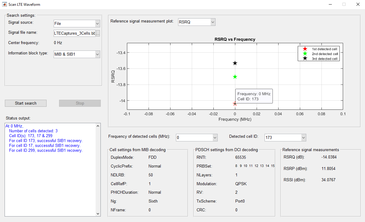
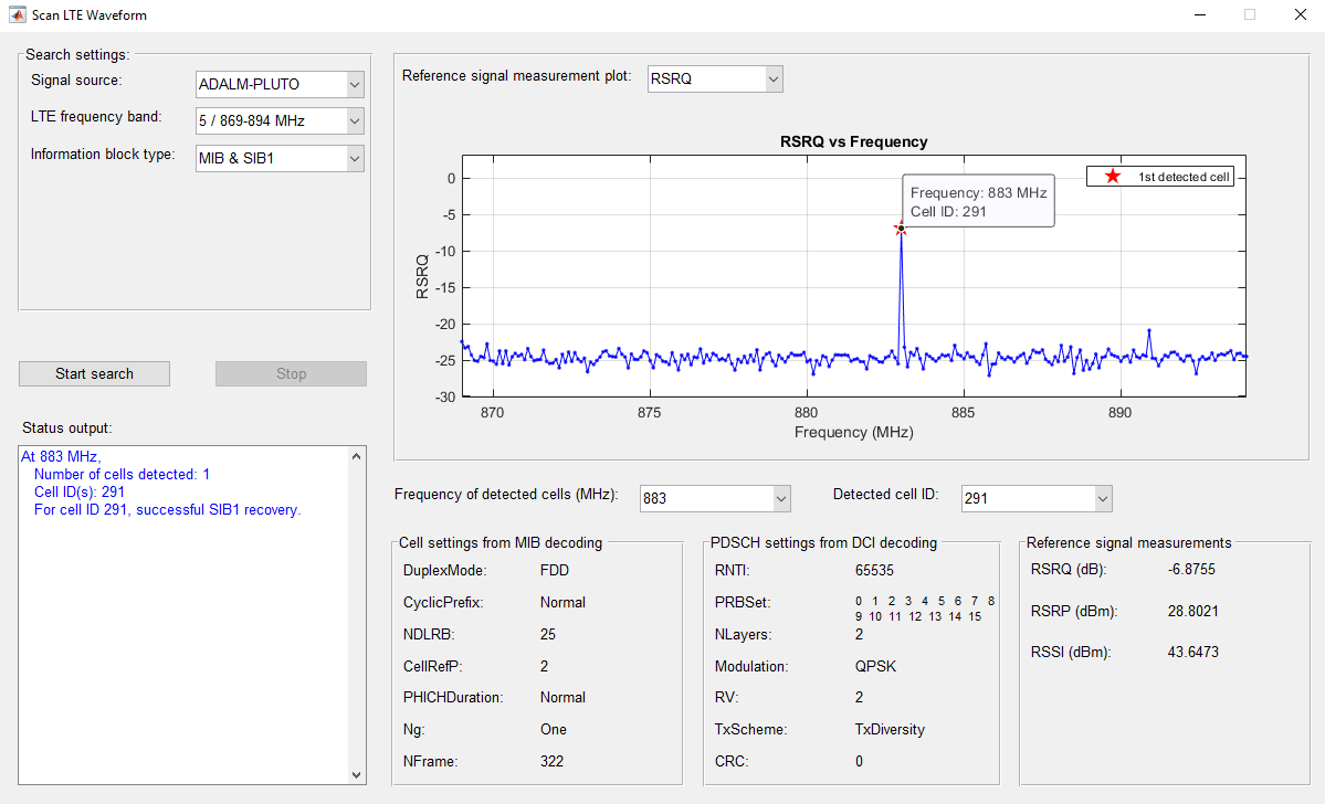
You can observe the detected cell information on the GUI as shown in these figures,
For the default run using File as Signal source:

Searching over a frequency range using SDR as Signal source:
