Gyroscope-Based Pedometer Using MATLAB Functions
This example shows how MATLAB Function blocks are used in Simulink® models to implement algorithms using MATLAB® functions. An Arduino® MKR1000 board is used to count the number of steps a person takes while walking. The pedometer is attached to the thigh of the person in such a way that the x-axis of the gyroscope is perpendicular to the direction of walking. The data from a gyroscope sensor is sent to an Android® device using the User Datagram Protocol (UDP).
Android devices provide wireless access and a user interface. The Arduino MKR1000 board senses the data using MPU-9250 sensor connected to the board. After calculating the steps, the board sends the data to the Android device connected to the Arduino board over Wi-Fi®.
Pedometer Algorithm
The pedometer algorithm is implemented inside the MATLAB function block in the Arduino model. You can use the model with other sensors after modifying the data read and sensor specific information. The data is read by the I2C device read functions inside the MATLAB function block.
While walking, one leg moves forward and the heel touches the ground. This is called an initial contact. Then, the body is pushed forward. The same leg lifts from the ground and moves forward and again the heel touches the ground, making the next initial contact. The duration between the first initial contact and the next initial contact is called a stride cycle.
Just before the leg lifts from the ground, the angular velocity of the thigh (on which the gyroscope is attached to) is zero. Then, the leg moves forward, and the angular velocity increases attaining maxima when the thigh is perpendicular to the ground. Again, the angular velocity decreases and reaches zero when the heel touches the ground, that is, when the leg makes the next initial contact. When the leg moves forward, the angular velocity has a positive gradient. In the stride cycle, when the leg moves backward pushing the body forward, the angular velocity has a negative gradient. Therefore, one stride cycle can be measured as the time between one negative gradient zero crossing point and the next.
After receiving an incoming frame, MATLAB identifies all local maxima, local minima, and zero crossings and then traverses the frame starting from the first zero crossing. If it is a negative gradient zero crossing, MATLAB expects a local minima next. After identifying the local minima, if MATLAB gets another zero crossing with positive gradient, MATLAB reads that as a valid step. The positive gradient zero crossing is the time when the other leg makes the first initial contact.
MATLAB counts all the valid zero crossings, which equals the number of steps. To validate a local maxima or minima, MATLAB uses a threshold value. The threshold is provided as an input to the MATLAB Function block. The threshold can be adjusted depending on the minimum walking speed of an individual.
Reusing the Model for Other Sensors
The Butterworth low pass filter defined inside the MATLAB Function block is set to a cut-off frequency of 5 Hz, which is sufficient for detecting the steps. Most gyroscopes allow you to configure the bandwidth and the output data rate. These parameters must be set according to the required bandwidth in the initialization block. Also, the sample rate of the MATLAB function block named Step Calculator, which reads gyroscope data from sensor, must be the same as the sampling rate of the Butterworth low pass filter. In this example, both are set to 20 Hz.
This example uses these Simulink models:
Arduino model: An Arduino board reads data from the MPU-9250 sensor and processes it inside a MATLAB Function block, and calculates the number of steps in real time.
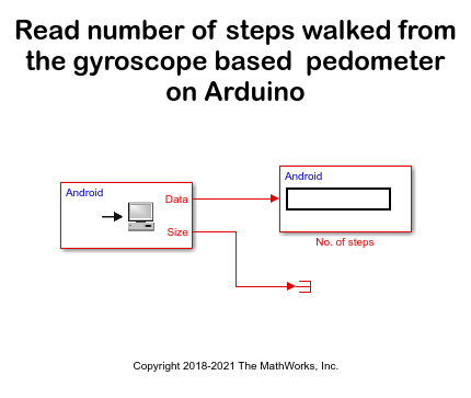
Android model: The UDP Receive block receives the data from the Arduino board over Wi-Fi.
With these models, you will:
Set up a network connection between the Arduino board and the Android device.
Configure and run Simulink models for the Arduino board and the Android device to calculate the number of steps taken.
Prerequisites
Before you start this example, install these MathWorks® products:
DSP System Toolbox™ along with MATLAB and Simulink
Simulink Support Package for Android Devices
Simulink Support Package for Arduino Hardware
MATLAB Support Package for Arduino Hardware
We recommend completing these examples:
Required Hardware
Arduino MKR1000/MKR WiFi 1010
Android device
MPU-9250 sensor
Set Up a Network Connection
Setup a network connection between the Arduino board and the Android device using UDP. The Arduino MKR1000/MKR WiFi 1010 board has an on-board Wi-Fi chip and can be used without any additional Wi-Fi hardware.
Open the
arduino_android_pedometer_MATLAB_codegenSimulink model.

Browse to Configuration Parameters > Hardware Implementation > Target hardware resources > WiFi properties.
Specify the SSID of your Wi-Fi network in the Service set identifier (SSID) parameter.
Select the WiFi encryption parameter based on your Wi-Fi network encryption settings. For more details on configuring the network settings for the Arduino Wi-Fi hardware, see Configure Network Settings for Wi-Fi (Simulink).
Connect the Android device to the same Wi-Fi network to which the Arduino board is connected.
Configure and Run Models on the Arduino Board and the Android Device
Open the
androidArduinoPedometerSimulink model.

Click the Deploy to Hardware button of the Android model to run the model on the Android device.
After the launch is complete, the app opens on the Android device.
Find the IP address of the Android device from the INFO pane of the app.
In the Arduino model, double-click the WiFi UDP Send block and set the Remote IP Address to the IP address of the Android device.
Click the Deploy to Hardware button to run this model on the Arduino board.
After the model is deployed on the Arduino board, you can see the step count values in the app.
More About
MATLAB Function Block Basics (Simulink)
References
Jayalath S, Abhayasinghe N, Murray I. A Gyroscope Based Accurate Pedometer Algorithm, October 2013.