BeagleBone Black PWM
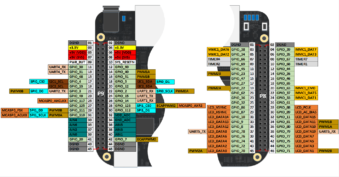
The BeagleBone® Black board has eight pulse-width modulation (PWM) output pins. Each PWM pin outputs a square waveform with variable frequency and duty cycle.
The minimum PWM output frequency is 0 Hz. The maximum PWM output
frequency is 400 MHz.
A duty cycle of 0 means that the waveform is always low. A duty
cycle of 1 means the waveform is always high.
To use a PWM pin, reconfigure one of the GPIO pins as a PWM pin.

Some of the internal PWMs are connected to two output pins: EHRPWM0A, EHRPWM0B, EHRPWM1A, EHRPWM1B, EHRPWM2A,
and EHRPWM2B. The remaining pins, ECAPPWM0 and ECAPPWM2,
are connected to one output pin.
You cannot configure more than one output pin at a time to a given internal PWM.
The hardware produces all PWM output waveforms relative to DGND.
Several electrically equivalent pins are connected to DGND, including
P9_01, P9_02, P8_01, and
P8_02.
Caution
Do not connect a PWM output pin directly to DGND.
Grounding a PWM pin can damage the board. Insert a load resistor in
series with components such as LEDs that do not present a resistive
load.