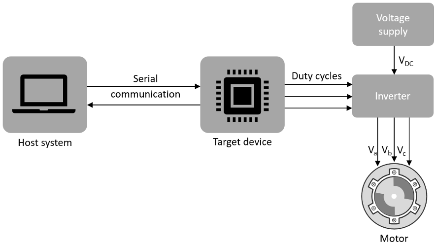
Host-Target Communication
Motor Control Blockset™ uses a communication interface between the host model and the target model to control the motor and observe feedback.
Host Model
The host model is a user interface for the controller hardware board. Run the host model on the host computer. Before you run the host model on the host computer, make sure to deploy the target model on the controller hardware board.
The host model commands, controls, and exchanges data with the target hardware. You can perform these operations using the host model available in the Motor Control Blockset:
Find the serial communication port (COM port) in the host system. For more details, see Find Communication Port section in this page.
Configure the serial port and baud rate by using the Serial Setup block.
Start or stop the motor.
Specify the motor speed.
View the debug or output signals that the host receives from the target by using the Time Scope and Display blocks.
Target Model
The target model runs on the controller hardware board. Deploy the target model to the embedded target hardware that controls the motor. The target model communicates with the host model to receive commands from the user (for example, the command to start or stop the motor). Some common operations that a target model available in Motor Control Blockset performs:
Serial communication with the host model to receive user commands and exchange binary data.
Read data from the position and current sensors attached to the motor and inverter.
Control motor speed and torque by running the control algorithms and processing the feedback.
Generate duty cycle inputs for the inverter.
Enable fast serial data monitoring for debugging the signals.
Serial Communication Blocks
The host and target models interact by using these Motor Control Blockset blocks that enable serial communication:
Host Serial Receive
Host Serial Setup
Host Serial Transmit
Using these blocks you can monitor, control, and customize the motor operation in real time. For example, you can view the debug signals, stop or start the motor, and change the motor speed without repeated deployment of the target model.
Fast Serial Data Monitoring
The Motor Control Blockset example models use the fast serial data monitoring algorithm, which performs control and diagnostic operations through the host model. This algorithm enables you to observe data from the target device at the same rate as the execution sample time (for example, PWM frequency of 20kHz). This, in turn, helps in diagnostics and analysis of transients.
Evaluation boards often provide serial communication over USB connections that enable fast serial transfers. The models running on the Texas Instruments® LaunchPad hardware boards send signals like Ia and Ib currents over the serial interface.
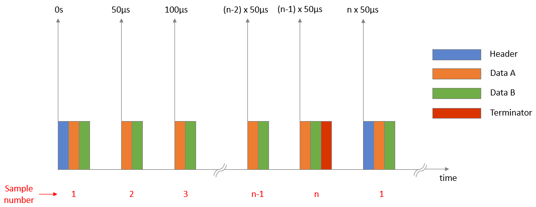
For example, consider a situation where a model needs to sample two signals A and B every 50 µs and send them to the host model for monitoring and debugging. To fulfil this requirement, the Motor Control Blockset examples divide the entire signal data into packets of 600 data points. Therefore, a packet from signal A combined with a signal B packet results in 1200 data points. Using this approach, the target hardware sequentially sends a pair of data packets (from signals A and B) to the host model. The target further groups these packet pairs into sections. Each section begins with a header and ends with a terminator. Following a header, the host model starts buffering the data points until it receives a terminator, after which Simulink® reads the buffered data that you can monitor.
To read the buffered data we select Enable blocking mode and
set Data size to [2 n] and Sample
time to n*50 µs in the Host Serial
Receive block parameter dialog box. Using this configuration, the
Host Serial Receive block reads 2×n data
points every n×50 µs. We select a value for n
such that the Simulink host model can run efficiently in real time.
Motor Control Blockset examples follow this approach because Simulink shows high efficiency when processing big packets of data at low data speeds and the target hardware (used by Motor Control Blockset) efficiently processes smaller data packets at higher data speeds.
Use the host model to receive these signals on your host computer. The Motor Control Blockset examples implementing Field Oriented Control (FOC) algorithm for the
F28379D LaunchPad use mcb_pmsm_foc_host_model_f28379d.slx.
Examples that implement the FOC algorithm for the F28069M targets, use
mcb_pmsm_foc_host_model_f28069m.slx. The Motor Control Blockset also provides other host models for the application-based examples.
Selecting COM port and baud rate
Select the appropriate COM port that matches your board in the Serial Setup block of the host model. Adjust the baud rate for your board:
| Texas Instruments LaunchPad | Baud Rate |
|---|---|
F28027 LaunchPad | 3.75e6 |
F28069 LaunchPad | 5.625e6 |
F28377S LaunchPad | 12e6 |
F28379D LaunchPad | 12e6 |
After you deploy the target model on the target device, run the host model and observe the debug signals update at 20 kHz, on the time scope. You can use the same technique to monitor other signals on other processors.
Note
SCI_A is usually connected to the FTDI chip that allows serial transfers over USB on the LaunchPad boards, docking stations, and ISO control cards.
Find Communication Port
Use these steps to find the serial communication port in the Device Manager of Windows® PC, after you connect the target hardware to your system:
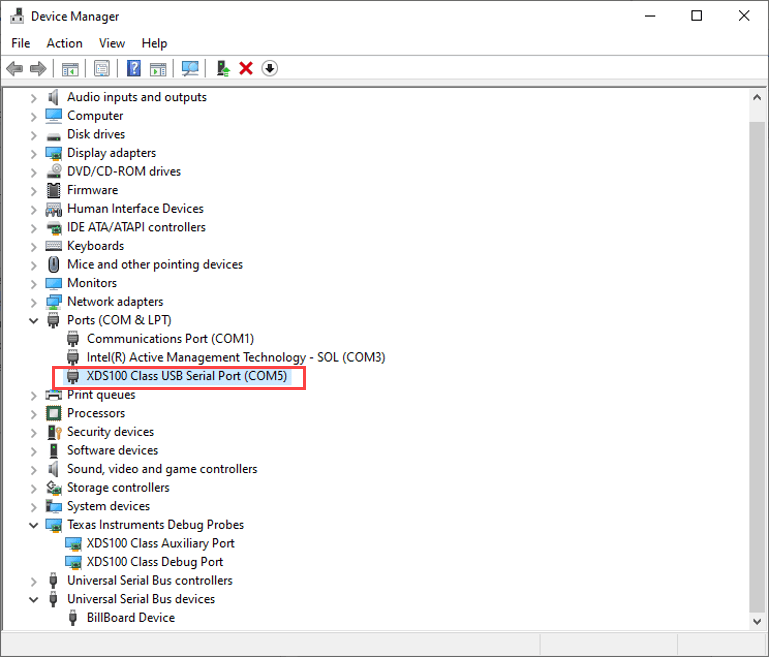
Open Device Manager on your Windows PC.
Look for an entry under Ports (COM & LPT) titled USB Serial Port (COMX), where X is a number. You can note down this number to configure the serial setup block in the host model.
If you face difficulty in finding the COM port, follow these steps to determine the COM port:
Open Device Manager on your Windows PC.
Look for an entry under Ports (COM & LPT) titled USB Serial Port (COMX), where X is a number. If there are multiple COM ports, you can disconnect and reconnect the C2000 board and observe the updates in Device Manager to determine the COM port.
Alternatively, follow these steps to determine the correct port name for the connected target hardware:
Right-click a communication port and click Properties.
In the Details tab, select Hardware Ids property.
If the port indicates the following IDs, the communication port belongs to the connected TI’s C2000™ controller hardware board:
VID: 0403
PID: A6D0
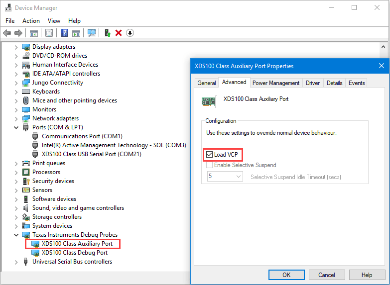
If you do not see or find the right port in Ports (COM & LPT), navigate to Texas Instruments Debug Probes and follow these steps:
Right-click XDS100 Class Auxiliary Port Properties and select Properties. Navigate to Advanced tab and select Load VCP.
Right-click XDS100 Class Debug Port Properties and select Properties. Navigate to Advanced tab and clear Load VCP.
Disconnect and reconnect the USB cable to the system and observe the updates in Device Manager to determine the COM port. The system now displays the COM port that belongs to the connected TI’s C2000 controller hardware board.
Tip
VCP stands for Virtual COM Port (for devices that support serial over USB communication).
If Texas Instruments Debug Probes do not appear in the Device Manager, expand Universal Serial Bus controllers in the Device Manager and follow these steps:
Right-click TI XDS 100 Channel B and select Properties. Navigate to Advanced tab and select Load VCP.
Right-click TI XDS 100 Channel A and select Properties. Navigate to Advanced tab and clear Load VCP.
Disconnect and reconnect the USB cable to the system and observe the updates in Device Manager to determine the COM port. The system now displays the COM port that belongs to the connected TI’s C2000 controller hardware board.
If Device Manager does not detect the target hardware, follow these steps:
Check that the target hardware is connected to the system.
Check if the device drivers are installed correctly. Generally, device drivers are installed with the Code Composer Studio™(CCS). Check if the CCS software is installed on your system. Alternatively, try re-installing the device drivers suggested by Texas Instruments.
Check if the serial connection cable is intact.
If the problem persists, try connecting the hardware to another system and check if Device Manager detects the hardware.
If you still face the problem, the target hardware may be faulty.
Add Debug Signals from Target Hardware
The host models included in the Motor Control Blockset examples provide a list of signals in the Debug signals section. You can select these signals and monitor them using the time scope available on the host model for debugging purposes.
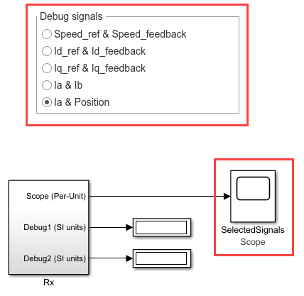
You can only add a pair of debug signals to this section at one time. Alternatively, you can modify the existing item in the list (for example, Speed_ref & Speed_feedback) to show the signals that you want. However, this procedure explains how to add a new pair of debug signals to the Debug signals section.
Double-click the Debug signals radio button to open the block parameters dialog box. Add a new state value (for example,
6-Id_ref_PU & Iq_ref_PU) to the existing list.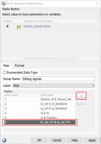
Open the block parameters dialog box of the Debug_signals constant block available in the TX subsystem of the host model. Set the constant to the new state value that you added in step 1 (for example, change the value
5to6).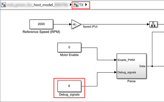
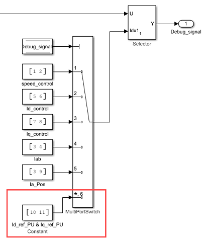
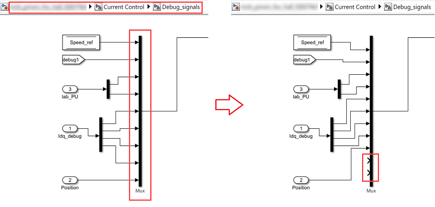
Open the target model associated with the host model and open the
Current Control/Debug_signalssubsystem.Add two more inputs to the mux block highlighted in the following figure:
Open the block parameters dialog box of the Selector block and set the Input port size parameter value to the number of inputs now available in the mux (for example, change the value from
9to11).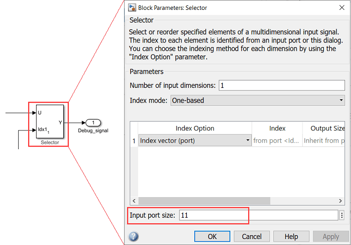
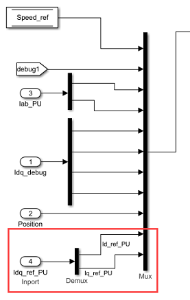
Connect the new signals (for example, Id_ref_PU and Iq_ref_PU) to the new mux ports that you added in step 4.
Open the block parameter dialog box of the Multiport Switch block and set the Number of data ports parameter to the number of debug signal pairs now available in the host model (for example, change the value from
5to6).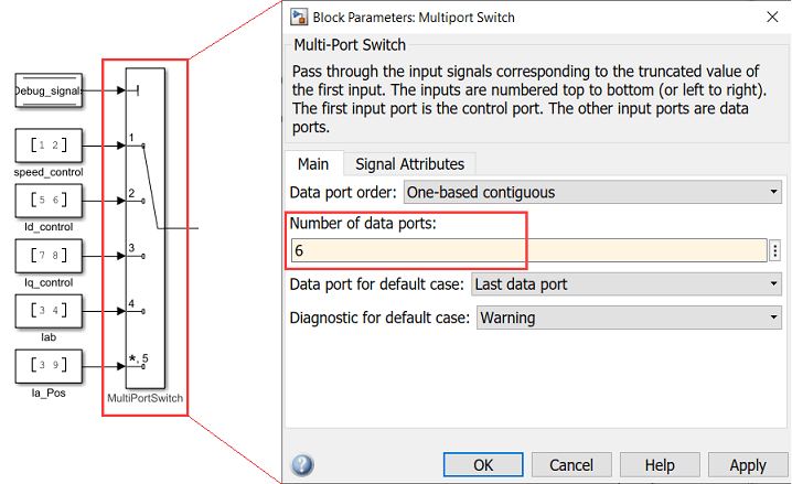
Add a constant block having a vector value that indicates the new signal positions on the mux (for example, use the vector
[10,
                            11]
for the mux inputs that you added in step 4). Connect this constant block to the newly added port on the Multiport Switch block.