How to Use Hall Validity and Hall Decoder Blocks
If you are using Hall position sensors to obtain the position feedback, follow this procedure to integrate the field-oriented control (FOC) algorithm with the Hall sensors and decode the rotor position and speed values.
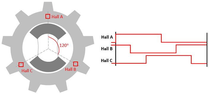
To determine the rotor position, direction of rotation, and an accurate rotor speed,
we need at least three Hall sensors inside the motor. To increase the accuracy of the
computed rotor position and speed values, you can use a motor that has more than three
Hall sensors. This procedure uses the model
mcb_pmsm_foc_hall_f28069m.slx as a reference. In addition, it
assumes a hardware setup that uses a permanent magnet synchronous motor (PMSM) with
three Hall sensors that are placed 120 degrees apart.
Configure eCAP Pins
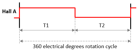
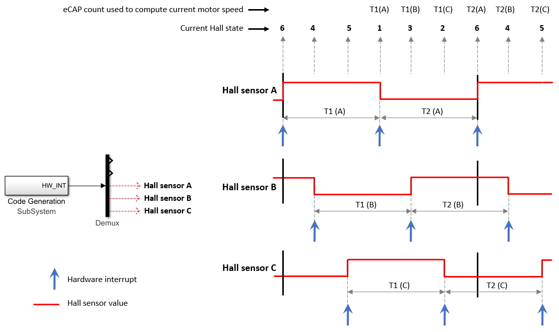
After you connect the three Hall sensors to the GPIO pins of the hardware, use the model configuration parameters dialog box to connect these GPIO pins to the eCAP module registers. The eCAP timer captures the time elapsed between two consecutive Hall value changes (0 to 1 or 1 to 0) for a single Hall sensor. You can use this time interval along with the current Hall state (Hall sensor A + Hall sensor B + Hall sensor C) to compute the rotor position and speed values. For example, for Hall sensor A, eCAP module should read eCAP1 register and record two time intervals (T1 and T2) between the Hall value changes that occur during a 360 electrical degree rotation cycle.
Similarly, eCAP2 and eCAP3 registers should read the Hall values and record the time intervals for Hall sensors 2 and 3 respectively. Use the following procedure to configure the eCAP connections.
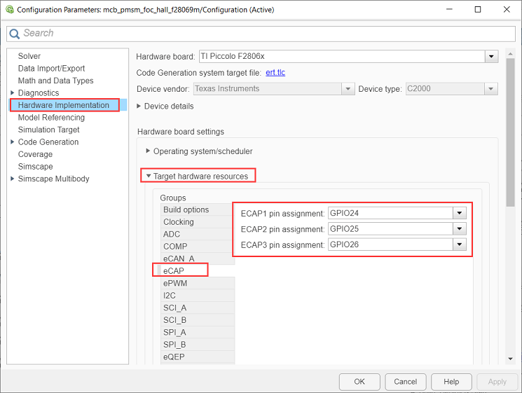
In the Simulink® model, use the Simulink toolstrip to open Model Settings to open the Configuration Parameters dialog box. In the Target hardware resources section of the Hardware Implementation tab, click the eCAP group. Use these fields to assign eCAP registers to the general-purpose I/O (GPIO) pins connected to the Hall sensors:
ECAP1 pin assignment — Select the GPIO pin connected to the Hall sensor A.
ECAP2 pin assignment — Select the GPIO pin connected to the Hall sensor B.
ECAP3 pin assignment — Select the GPIO pin connected to the Hall sensor C.
Generate Interrupts for Hall Value Transitions
For each Hall sensor, the eCAP timer should reset and start when the Hall value changes (transitions from 0 to 1 or 1 to 0). A hardware interrupt can trigger this action when a Hall value changes. Use this procedure to generate separate set of hardware interrupts for the three eCAP registers (connected to the three Hall sensors).
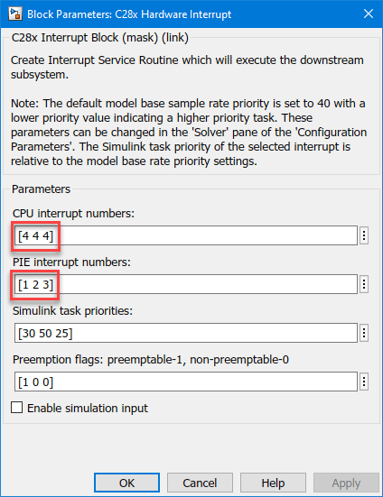
Use the Simulink browser to add the C28x Hardware Interrupt block from Embedded Coder Support Package for Texas Instruments C2000 Processors > Scheduling.
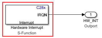
Use the C28x Interrupt Block Parameters dialog box to configure the block. Set the CPU interrupt numbers and PIE interrupt numbers parameters to configure the block to trigger an interrupt for each Hall value change (transition from 0 to 1 or 1 to 0) for every Hall sensor. In addition, this configures the block to interface with the configured eCAP registers to detect a Hall value change.
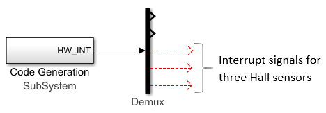
Place the C28x Hardware Interrupt block inside a subsystem named Code Generation and connect it to a demultiplexer to generate separate hardware interrupt signals for the three Hall sensors.
Service Generated Interrupts
Service the hardware interrupt signals so that for each interrupt:
The eCAP timer (for a Hall sensor) resets and restarts.
The algorithm captures the current Hall state (Hall sensor A + Hall sensor B + Hall sensor C).
Use this procedure to implement the algorithm to service the hardware interrupts:
Use the Simulink browser to add the eCAP block from Embedded Coder Support Package for Texas Instruments C2000 Processors > C280x.
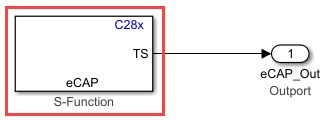
Place this block inside a subsystem named Code generation. This subsystem captures the time elapsed (timer count) between two Hall value changes for a single Hall sensor.
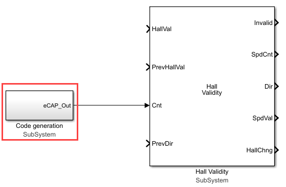
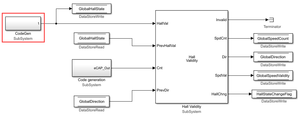
Use the Simulink browser to add the Hall Validity block from Motor Control Blockset > Sensor Decoders. Connect the Code generation subsystem to the Cnt input port of the Hall Validity block.
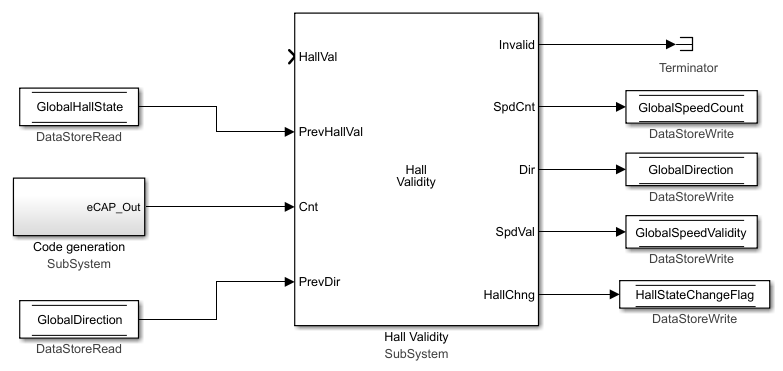
Create these global variables (by using Data Store Memory, Data Store Read, and Data Store Write blocks):
GlobalHallState — Stores the Hall state (Hall sensor A + Hall sensor B + Hall sensor C).
GlobalDirection — Stores the direction of the rotor spin (either +1 or –1 indicating positive or negative direction of rotation, respectively).
GlobalSpeedCount — Stores the eCAP timer output.
GlobalSpeedValidity — Stores either 0 (indicating an invalid speed count) or 1 (indicating a valid speed count).
HallStateChangeFlag — Stores 1 (to indicate that a Hall value has changed) or 0 (to indicate that speed and position computation for the previous Hall state (Hall sensor A + Hall sensor B + Hall sensor C) is complete).
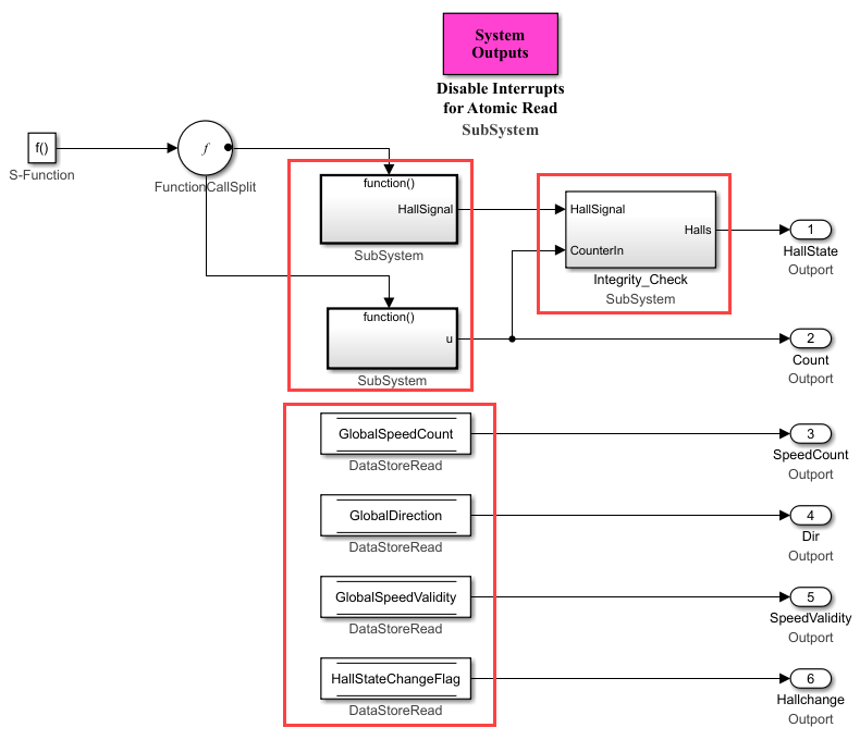
Connect these variables to the Hall Validity block as shown in the following figure:
Use the Simulink browser to add the Memory Copy block from Embedded Coder Support Package for Texas Instruments C2000 Processors > Memory Operations. In the Memory Copy block parameters dialog box, set the Copy from parameter to
Specified
                            source code symbol
. Use the Source code symbol parameter to specify the variable name available in the source code symbol table that stores the current Hall state.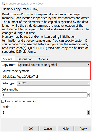
Connect the Memory Copy block output to an outport.
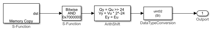
Place these blocks inside a subsystem named CodeGen. Therefore, this subsystem outputs the current Hall state.
Connect the CodeGen subsystem to the Hall Validity block as shown in the following figure:
Integrate the Hall Validity block and the entire hardware interrupt service algorithm into a single subsystem named Hall sensor A. Add the Trigger block from the Simulink > Ports & Subsystems library to this subsystem and set the Trigger type parameter to
function-call. Rename the trigger block as eCAP1 Interrupt.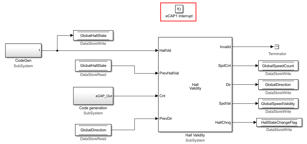
The trigger block acts as the hardware interrupt signal for Hall sensor A. When the Hall sensor A subsystem receives an interrupt (indicating a Hall sensor A value change), the hardware interrupt service algorithm resets the eCAP timer to output the recorded timer count (during the previous Hall state) and also captures the current Hall state.
Similarly, create the subsystems Hall sensor B and Hall sensor C containing the hardware interrupt service algorithms for Hall sensors B and C, respectively. Connect these subsystems to the Code Generation subsystem that you created in the section Generate Interrupts for Hall Value Transitions.

Compute Electrical Position and Mechanical Speed
Use the following procedure to add the position and speed computation algorithm to
the Current Control subsystem. For more details, see the model
mcb_pmsm_foc_hall_f28069m.slx as a reference.
Add the algorithm used in steps 4 and 5 of the section Service Generated Interrupts in the current controller. The algorithm enables the current controller to read the current Hall state. Add the Trigger block from the Simulink > Ports & Subsystems library to this subsystem and set the Trigger type parameter to
function-call. Place this algorithm in a subsystem.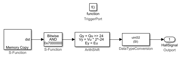
Use the Memory Copy blocks (from Embedded Coder Support Package for Texas Instruments C2000 Processors > Memory Operations) to read the three eCAP timer counter values. Add the Trigger block from the Simulink > Ports & Subsystems library to this subsystem and set the Trigger type parameter to
function-call. Place this algorithm in a subsystem.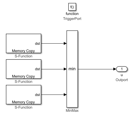
Integrate the two function-call subsystems (that you crated in steps 1 and 2), global variables, and an integrity check algorithm for eCAP counter and Hall state values into a subsystem named Atomic Hall Reading.
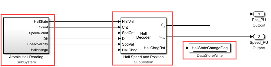
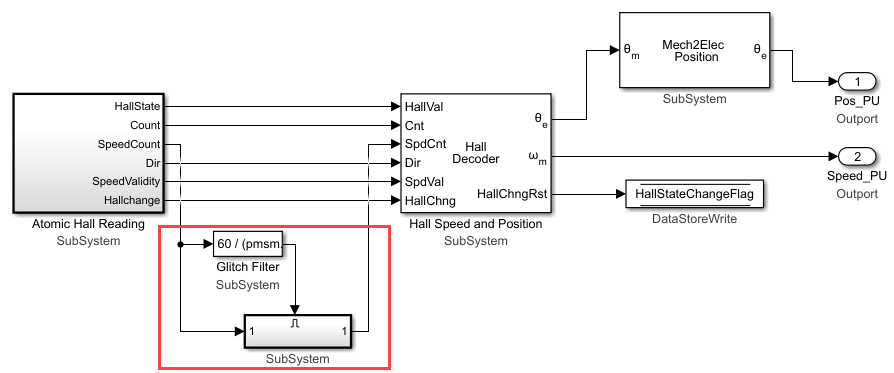
Use the Simulink browser to add the Hall Speed and Position block from Motor Control Blockset > Sensor Decoders. Connect this block, the Atomic Hall Reading subsystem, and the HallStateChangeFlag variable as shown in the following figure:
Use the Simulink browser to add the Mechanical to Electrical Position block from Motor Control Blockset > Sensor Decoders. In the block parameters dialog box enter the variable pmsm.PositionOffset for the Mechanical offset parameter.
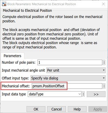
The variable pmsm.PositionOffset (available in the model initialization script associated with the reference model
mcb_pmsm_foc_hall_f28069m.slx) stores the offset value for the Hall sensor. We use the Mechanical to Electrical Position to apply this offset to the computed electrical position value.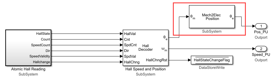
Add a glitch filter to the computed speed count value. This filter rejects low values of computed speed count. This enables the motor to run at speeds greater than ten times the base speed.
Add the resulting algorithm inside the
Current Control/Input
                            Scaling
subsystem of the reference Simulink model. For more details, seemcb_pmsm_foc_hall_f28069m.slx.
You can also select a web site from the following list
Americas
- América Latina (Español)
- Canada (English)
- United States (English)
Europe
- Belgium (English)
- Denmark (English)
- Deutschland (Deutsch)
- España (Español)
- Finland (English)
- France (Français)
- Ireland (English)
- Italia (Italiano)
- Luxembourg (English)
- Netherlands (English)
- Norway (English)
- Österreich (Deutsch)
- Portugal (English)
- Sweden (English)
- Switzerland
- United Kingdom (English)
Asia Pacific
- Australia (English)
- India (English)
- New Zealand (English)
- 中国
- 日本Japanese (日本語)
- 한국Korean (한국어)