主要内容

DCDC Voltage Controller

R2026b

Regulate output voltage of a DC-DC nonisolated converter

Since R2026b

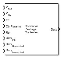
  • DCDC Voltage Controller block icon.

Libraries:
Power Converter Control with Motor Control Blockset / Control / DC-DC Non-Isolated

Description

Add-On Required: This feature requires the Power Converter Control with Motor Control Blockset add-on.

The DCDC Voltage Controller block implements a discrete-time closed-loop voltage regulator for a DC-DC non-isolated converters. The block supports both PI controller and Type 2 compensator. The CtrlType field of the CtrlParams input bus determines the controller type at runtime, so you choose the controller type in the connected DCDC Controller Parameters block rather than in this block.

The block computes the voltage error as the difference between the reference voltage at VRef and the measured feedback voltage at VFb. It applies the discrete controller to the error and adds the feedforward signal at FF to the controller output before applying the output saturation limits. To improve transient response to predictable disturbances such as changes in input voltage, use the feedforward input. For a buck converter, a common feedforward signal is the ratio of input voltage to output voltage.

The block supports bumpless transfer through the Rst and DutyInit ports. When Rst is nonzero, the block sets the integrator state to the value at DutyInit and preloads the integrator state so the output resumes from that duty cycle when you release the reset. Use these ports to initialize the controller to a known duty cycle at startup or after a fault condition to avoid large transient steps in the duty cycle command.

To use this block, connect the CtrlParams output of a DCDC Controller Parameters block that is configured for the same converter topology and operating point. Connect a voltage reference signal to VRef and the measured converter output voltage to VFb. Connect the Duty output to the duty cycle input of a PWM generation block in your converter model.

Examples
Ports

Input

expand all

Desired output voltage setpoint in volts, specified as a scalar. The block computes the voltage error as VRef minus VFb and applies the controller to drive the output toward this setpoint. Connect this port to the voltage reference signal in your model, such as a constant block set to the nominal output voltage or a variable reference for dynamic regulation.

Data Types: double | single

Measured converter output voltage in volts, specified as a scalar. Connect this port to a voltage sensor output in your model. The block subtracts this value from VRef to compute the control error that drives the PI or Type 2 compensator.

Data Types: double | single

Feedforward signal added directly to the controller output before the output saturation limits are applied, specified as a scalar. Use the feedforward input to improve transient response to known disturbances such as input voltage changes. If no feedforward is needed, set to zero.

Data Types: double | single

Controller parameters bus containing the discrete-time gains and coefficients, specified as a bus. Connect the CtrlParams output of a DCDC Controller Parameters block configured for the same converter topology and operating point. The block reads the CtrlType field of the bus at runtime to determine whether to apply the PI or Type-2 compensator algorithm.

Data Types: bus

Boolean reset signal that clears the integrator state when nonzero, specified as a scalar. When you assert Rst, the block sets the controller output to the value at DutyInit and preloads the integrator state accordingly. To enable bumpless transfer when control resumes, use this port to initialize the controller at startup or after a fault.

Data Types: double | single

Initial duty cycle value applied when Rst is asserted, specified as a scalar in the range [0, 1]. This value preloads the integrator state so the output starts at a known duty cycle rather than zero to enable bumpless transfer after a reset event. To minimize the transient step when you first enable control, set this to the expected steady-state duty cycle at your operating point.

Data Types: double | single

Upper saturation limit for the duty cycle output, specified as a scalar in the range [0, 1]. The block clamps the controller output to this maximum value before outputting the duty cycle command. To prevent inductor saturation or excessive switch stress, set this to the maximum allowable duty cycle for your converter. For most buck converters, use a value slightly below 1 to allow the bootstrap gate driver circuit to recharge.

Data Types: double | single

Lower saturation limit for the duty cycle output, specified as a scalar in the range [0, 1]. The block clamps the controller output to this minimum value before outputting the duty cycle command. Typically set to 0 for a unidirectional converter. If your converter requires a minimum on-time for proper bootstrap operation or continuous-conduction-mode control, set to a small positive value.

Data Types: double | single

Output

expand all

Duty cycle command in the range [DutyLowerLimit, DutyUpperLimit], output as a scalar. Connect this signal to the duty cycle input of a PWM generation block to drive the converter switch. A value of 1 corresponds to 100% duty cycle. The output is clamped by the upper and lower saturation limits supplied through the DutyUpperLimit and DutyLowerLimit input ports.

Data Types: double | single

Parameters

expand all

To edit block parameters interactively, use the Property Inspector. From the Simulink® Toolstrip, on the Simulation tab, in the Prepare gallery, select Property Inspector.

Select None to apply no anti-windup protection. The integrator continues to accumulate error even when the duty cycle output is saturated. Use this option only if the duty cycle limits are rarely reached, or if external logic prevents sustained saturation.

Select Back-calculation to feed the difference between the unsaturated and saturated output back to the integrator input, scaled by the back-calculation coefficient Kb. This method unwinds the integrator while the output is saturated. The Back-calculation coefficient (Kb) parameter controls the rate of unwinding.

Select Clamping to disable the integrator update when the output is saturated and the error signal would push the output further into saturation. This method stops accumulation at the saturation boundary without requiring an additional coefficient.

Programmatic Use

To set the block parameter value programmatically, use the set_param function.

Parameter: AntiWindupMethod
Values: "None" (default) | "Back-calculation" | "Clamping"

Example: set_param(gcb,"AntiWindupMethod","Clamping")

Gain for the back-calculation anti-windup method, specified as a positive scalar. The block uses this value to scale the feedback signal from the output saturation error back to the integrator input. A larger value causes the integrator to unwind faster when the duty cycle output reaches its saturation limits, reducing the time to recover from a saturated state. However, too large a value can cause oscillation in the integrator state during recovery. Start with a value of 1 and increase it if you observe slow recovery from saturation. Decrease it if you observe oscillations following a saturation event.

Dependencies

This parameter is visible when Anti-windup Method is set to Back-calculation.

Programmatic Use

To set the block parameter value programmatically, use the set_param function.

Parameter: BackCalCoeff
Values: "1" (default) | positive scalar in quotes
Data Types: char | string

Example: set_param(gcb,"BackCalCoeff","2")

Extended Capabilities

expand all

C/C++ Code Generation
Generate C and C++ code using Simulink® Coder™.

Version History

Introduced in R2026b