Review Model Predictive Controller for Stability and Robustness Issues
You can review your model predictive controller design for potential stability and robustness problems. To do so:
At the command line, use the
reviewfunction.In MPC Designer, on the Tuning tab, in the Analysis section, click Review Design.
In both cases, the software generates a report that shows the results of the following tests:
MPC Object Creation — Test whether the controller specifications generate a valid MPC controller. If the controller is invalid, additional tests are not performed.
QP Hessian Matrix Validity — Test whether the MPC quadratic programming (QP) problem for the controller has a unique solution. You must choose cost function parameters (penalty weights) and horizons such that the QP Hessian matrix is positive-definite.
Closed-Loop Internal Stability — Extract the
Amatrix from the state-space realization of the unconstrained controller, and then calculate its eigenvalues. If the absolute value of each eigenvalue is less than or equal to1and the plant is stable, then your feedback system is internally stable.Closed-Loop Nominal Stability — Extract the
Amatrix from the discrete-time state-space realization of the closed-loop system; that is, the plant and controller connected in a feedback configuration. Then calculate the eigenvalues ofA. If the absolute value of each eigenvalue is less than or equal to1, then the nominal (unconstrained) system is stable.Closed-Loop Steady-State Gains — Test whether the controller forces all controlled output variables to their targets at steady state in the absence of constraints.
Hard MV Constraints — Test whether the controller has hard constraints on both a manipulated variable and its rate of change, and if so, whether these constraints may conflict at run time.
Other Hard Constraints — Test whether the controller has hard output constraints or hard mixed input/output constraints, and if so, whether these constraints may become impossible to satisfy at run time.
Soft Constraints — Test whether the controller has the proper balance of hard and soft constraints by evaluating the constraint ECR parameters.
Memory Size for MPC Data — Estimate the memory size required by the controller at run time.
You can also programmatically assess your controller design using the review function. In this case, the pass/fail testing results are returned as a structure and the testing report is suppressed.
The following example shows how to review your controller design at the command line and address potential design issues.
Plant Model
The application in this example is a fuel gas blending process. The objective is to blend six gases to obtain a fuel gas, which is then burned to provide process heating. The fuel gas must satisfy three quality standards in order for it to burn reliably and with the expected heat output. The fuel gas header pressure must also be controlled. Thus, there are four controlled output variables. The six manipulated variables are the feed gas flow rates.
The plant inputs are:
Natural gas (
NG)Reformed gas (
RG)Hydrogen (
H2)Nitrogen (
N2)Tail gas 1 (
T1)Tail gas 2 (
T2)
The plant outputs are:
High heating value (
HHV)Wobbe index (
WI)Flame speed index (
FSI)Header pressure (
P)
For more information on the fuel gas blending problem, see [1].
Use the following linear plant model as the prediction model for the controller. This state-space model, applicable at a typical steady-state operating point, uses the time unit hours.
A = diag([-28.6120 -28.6822 -28.5134  -0.0281 -23.2191 -23.4266 ...
          -22.9377  -0.0101 -26.4877 -26.7950 -27.2210  -0.0083 ...
          -23.0890 -23.0062 -22.9349  -0.0115 -25.8581 -25.6939 ...
          -27.0793  -0.0117 -22.8975 -22.8233 -21.1142  -0.0065]);
B = zeros(24,6);
B( 1: 4,1) = [4 4 8 32]';
B( 5: 8,2) = [2 2 4 32]';
B( 9:12,3) = [2 2 4 32]';
B(13:16,4) = [4 4 8 32]';
B(17:20,5) = [2 2 4 32]';
B(21:24,6) = [1 2 1 32]';
C = [diag([ 6.1510  7.6785 -5.9312 34.2689]) ...
     diag([-2.2158 -3.1204  2.6220 35.3561]) ...
     diag([-2.5223  1.1480  7.8136 35.0376]) ...
     diag([-3.3187 -7.6067 -6.2755 34.8720]) ...
     diag([-1.6583 -2.0249  2.5584 34.7881]) ...
     diag([-1.6807 -1.2217  1.0492 35.0297])];
D = zeros(4,6);
Plant = ss(A,B,C,D);
By default, all the plant inputs are manipulated variables.
Plant.InputName = {'NG','RG','H2','N2','T1','T2'};By default, all the plant outputs are measured outputs.
Plant.OutputName = {'HHV','WI','FSI','P'};To reflect sensor delays, add transport delays to the plant outputs.
Plant.OutputDelay = [0.00556 0.0167 0.00556 0];
Initial Controller Design
Construct an initial model predictive controller based on the design requirements. First, for clarity, disable MPC command-window messages.
MPC_verbosity = mpcverbosity('off');Create a controller with a:
Sample time,
Ts, of20seconds, specified in hours, which corresponds to the sample time of the sensors.Prediction horizon,
p, of39control intervals, which is approximately equal to the plant settling time.Control horizon,
m, that uses four blocked moves with lengths of2,6,12, and19control intervals.
Ts = 20/3600;
p = 39;
m = [2 6 12 19];
Obj = mpc(Plant,Ts,p,m);
Specify the output measurement noise and nonzero nominal operating point for the controller.
Obj.Model.Noise = ss(0.001*eye(4));
Obj.Model.Nominal.Y = [16.5 25 43.8 2100];
Obj.Model.Nominal.U = [1.4170 0 2 0 0 26.5829];
Specify lower and upper bounds for each manipulated variable (MV). Since all the manipulated variables are flow rates of gas streams, their lower bounds are zero. By default, all the MV constraints are hard (MinECR = 0 and MaxECR = 0).
MVmin = zeros(1,6);
MVmax = [15 20 5 5 30 30];
for i = 1:6
    Obj.MV(i).Min = MVmin(i);
    Obj.MV(i).Max = MVmax(i);
end
Specify lower and upper bounds for the manipulated variable increments. The bounds are set large enough to allow full range of movement in one interval. By default, all the MV rate constraints are hard (RateMinECR = 0 and RateMaxECR = 0).
for i = 1:6
    Obj.MV(i).RateMin = -MVmax(i);
    Obj.MV(i).RateMax =  MVmax(i);
end
Specify lower and upper bounds for each plant output variable (OV). By default, all the OV constraints are soft (MinECR = 1 and MaxECR = 1).
OVmin = [16.5 25 39 2000];
OVmax = [18.0 27 46 2200];
for i = 1:4
    Obj.OV(i).Min = OVmin(i);
    Obj.OV(i).Max = OVmax(i);
end
Specify tuning weights for the manipulated variables. MV weights are specified based on the known costs of each feed stream. Doing so tells MPC controller how to move the six manipulated variables to minimize the cost of the blended fuel gas. The weights are normalized such that the maximum weight is approximately 1.0.
Obj.Weights.MV = [54.9 20.5 0 5.73 0 0]/55;
Specify tuning weights for the manipulated variable increments. These weights are small relative to the maximum MV weight so that the MVs are free to vary.
Obj.Weights.MVrate = 0.1*ones(1,6);
Specify tuning weights for the plant output variables. The OV weights penalize deviations from specified setpoints and would normally be large relative to the other weights. For this example, first consider the default values, which equal the maximum MV weight.
Obj.Weights.OV = [1,1,1,1];
Improve the Initial Design
Review the initial controller design. The review function generates and opens a report in the Web Browser window.
review(Obj)
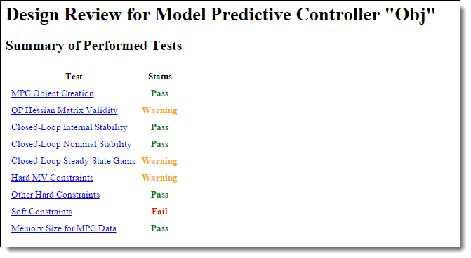
The review summary lists three warnings and one error. Review the warnings and error in order. Click QP Hessian Matrix Validity and scroll down to the warning, which indicates that the plant signal magnitudes differ significantly. Specifically, the pressure response is much larger than the other signals.
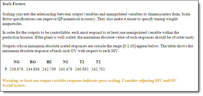
The OV spans indicated by the specified OV bounds are quite different, and the pressure span is two orders of magnitude larger than the others. It is good practice to account for the expected differences in signal magnitudes by specifying MPC scale factors. Since the MVs are already weighted based on relative cost, specify scale factors only for the OVs.
Calculate OV spans.
OVspan = OVmax - OVmin;
Use these spans as scale factors.
for i = 1:4
    Obj.OV(i).ScaleFactor = OVspan(i);
end
To verify that setting output scale factors fixes the warning, review the updated controller design.
review(Obj)
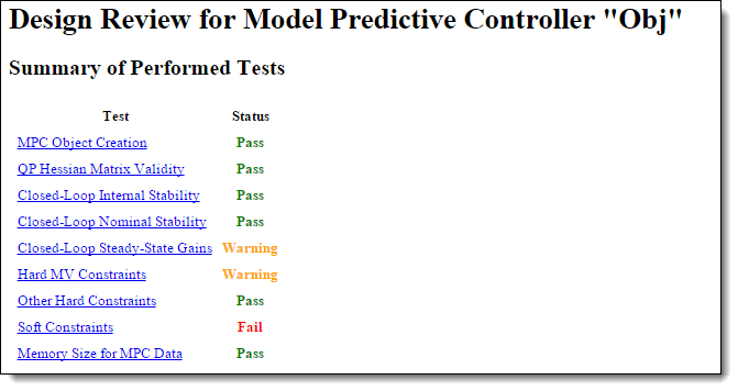
The next warning indicates that the controller does not drive the OVs to their targets at steady state. To see a list of the nonzero gains, click Closed-Loop Steady-State Gains.
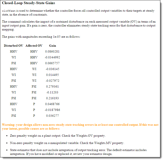
The first entry in the list shows that adding a sustained disturbance of unit magnitude to the HHV output would cause the HHV output to deviate about 0.0860 units from its steady-state target, assuming no constraints are active. The second entry shows that a unit disturbance in WI would cause a steady-state deviation, or offset, of about -0.0345 in HHV, and so on.
Since there are six MVs and only four OVs, excess degrees of freedom are available. Therefore, you might expect the controller to have no steady-state offsets. However, the specified nonzero MV weights, which were selected to drive the plant toward the most economical operating condition, are causing nonzero steady-state offsets.
Nonzero steady-state offsets are often undesirable but are acceptable in this application because:
The primary objective is to minimize the blend cost. The gas quality (
HHV, and so on) can vary freely within the specified OV limits.The small offset gain magnitudes indicate that the impact of disturbances is small.
The OV limits are soft constraints. Small, short-term violations are acceptable.
View the second warning by clicking Hard MV Constraints. This warning indicates a potential conflict in hard constraints.
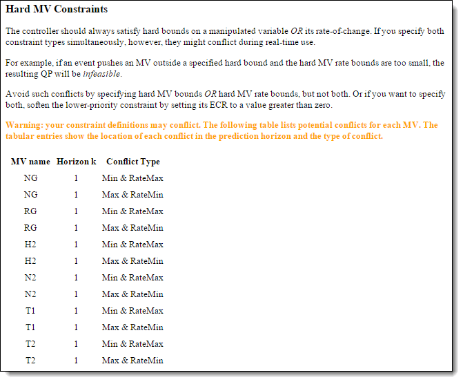
If an external event causes NG to go far below its specified minimum, the constraint on its rate of increase might make it impossible to return the NG within bounds in one control interval. In other words, if you specify both MV.Min and MV.RateMax, the controller would not be able to find an optimal solution if the most recent MV value is less than (MV.Min - MV.RateMax). Similarly, there is a potential conflict when you specify both MV.Max and MV.RateMin.
An MV constraint conflict would be unlikely in the gas blending application. However, it is good practice to eliminate the possibility by softening one of the two constraints. Since the MV minimum and maximum values are physical limits and the increment bounds are not, soften the increment bounds.
for i = 1:6
    Obj.MV(i).RateMinECR = 0.1;
    Obj.MV(i).RateMaxECR = 0.1;
end
Review the updated controller design.
review(Obj)
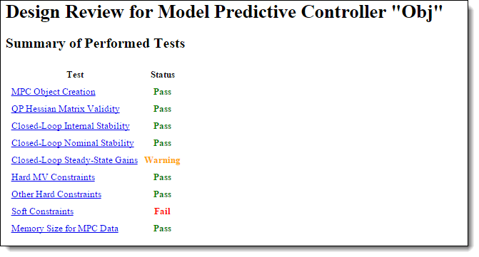
The MV constraint conflict warning is fixed.
To view the error message, click Soft Constraints.
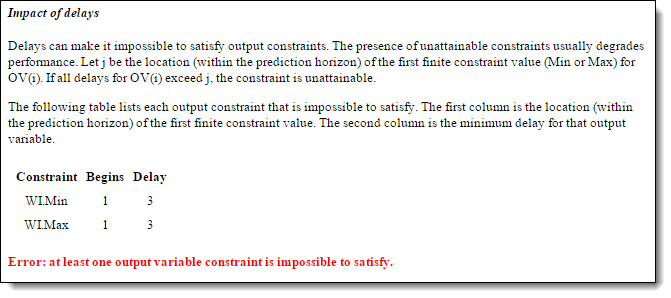
The delay in the WI output makes it impossible to satisfy bounds on that variable within the first three control intervals. The WI bounds are soft, but it is poor practice to include unattainable constraints in a design. Therefore, modify the WI bound specifications such that it is unconstrained until the fourth prediction horizon step.
Obj.OV(2).Min = [-Inf(1,3) OVmin(2)];
Obj.OV(2).Max = [ Inf(1,3) OVmax(2)];
Rerunning the review command verifies that this change eliminates the error message, as shown in the next step.
Assess Impact of Zero Output Weights
Given that the design requirements allow the OVs to vary freely within their limits, consider removing their penalty weights.
Obj.Weights.OV = zeros(1,4);
Review the impact of this design change.
review(Obj)
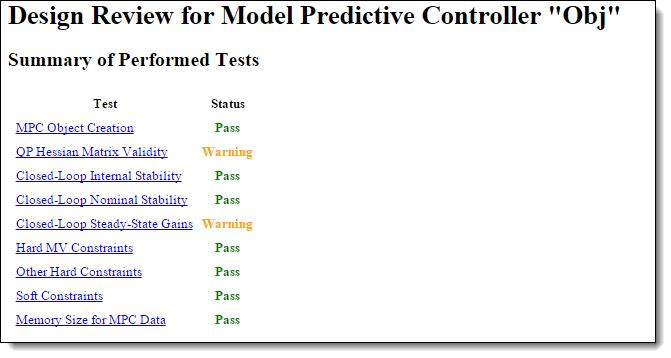
There is a new warning regarding the QP Hessian matrix validity. To see the warning details, click QP Hessian Matrix Validity.

The review flags the zero weights on all four output variables. Since the zero weights are consistent with the design requirements and the other Hessian tests indicate that the quadratic programming problem has a unique solution, this warning can be ignored. To see the second new warning, click Closed-Loop Steady-State Gains. The warning shows another consequence of setting the four OV weights to zero. When an OV is not penalized by a weight, the controller ignores any output disturbance added to the OV and passes the disturbance through with no attenuation.
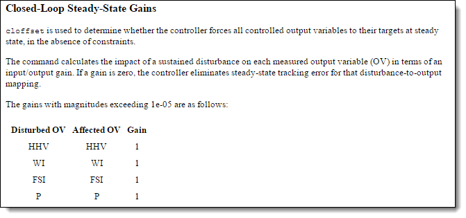
Since it is a design requirement, nonzero steady-state offsets are acceptable as long as the controller is able to hold all the OVs within their specified bounds. Therefore, it is a good idea to examine how easily the soft OV constraints can be violated when disturbances are present.
Review Soft Constraints
To see a list of soft constraints, click Soft Constraints. In this example, the soft constraints are the upper and lower bound on each OV.

The Impact Factor column shows that using the default MinECR and MaxECR values give the pressure (P) a much higher priority than the other OVs. To make the priorities more comparable, increase the pressure constraint ECR values, and adjust the others as well. For example:
Obj.OV(1).MinECR = 0.5;
Obj.OV(1).MaxECR = 0.5;
Obj.OV(3).MinECR = 3;
Obj.OV(3).MaxECR = 3;
Obj.OV(4).MinECR = 80;
Obj.OV(4).MaxECR = 80;
Review the impact of this design change.
review(Obj)
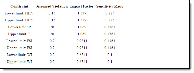
In the Sensitivity Ratio column, all the sensitivity ratios are now less than unity, which means that the soft constraints receive less attention than other terms in the MPC objective function, such as deviations of the MVs from their target values. Therefore, it is likely that an output constraint violation would occur.
To give the output constraints higher priority than other MPC objectives, increase the Weights.ECR parameter from the default, 1e5, to a higher value, which hardens all the soft OV constraints.
Obj.Weights.ECR = 1e8;
Review the impact of this design change.
review(Obj)
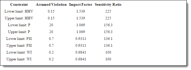
The controller is now more sensitive to output constraint violations than to errors in target tracking by a factor of 100.
Review Data Memory Size
To see the estimated memory size required to store the MPC data matrices used on hardware, click Memory Size for MPC Data.
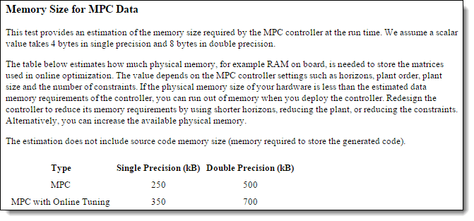
In this example, if the controller is running using single precision, it requires 250 KB of memory to store its matrices. If the controller memory size exceeds the memory available on the target system, redesign the controller to reduce its memory requirements. Alternatively, increase the memory available on the target system.
Restore the MPC verbosity level.
mpcverbosity(MPC_verbosity);
References
[1] Muller C. J., I. K. Craig, and N. L. Ricker. "Modeling, validation, and control of an industrial fuel gas blending system." Journal of Process Control. Vol. 21, Number 6, 2011, pp. 852-860.
See Also
Apps
Functions
review|trim|cloffset|sim|ss|tf|zpk|size|d2d|getindist|getoutdist|setindist|setoutdist