Model Continuous Time Delta Sigma Modulator based ADC
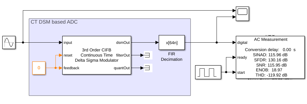
This example shows how to model a Continuous Time Delta Sigma Modulator (CT DSM) based ADC using the Continuous Time Delta Sigma Modulator block from Mixed-Signal Blockset™.
CT DSMs are well suited for high bandwidth applications since they employ continuous time integrators. CT DSMs also possess inherent anti-aliasing property which can reduce system cost since such a system can do away with an anti-aliasing filter or use a less complicated anti-aliasing filter. Open the model thirdOrderCTDSM which consists of the CT DSM block, FIR filter and the ADC AC Measurement block. The input sinusoid source is set to a frequency of 1 kHz.
open_system('thirdOrderCTDSM.slx')
The CT DSM block is configured as a third order Cascade of Integrators with FeedBack (CIFB) DSM. The system bandwidth is set to 10 kHz with an OSR of 64 and the number of quantizer levels is set to 16. In the "Impairment" tab, you can set a finite gain for the integrator opamp and enable noise impairment. "Advanced" tab has parameters to set optimization settings for NTF synthesis as per Schreier's Delta-Sigma Toolbox, passband options i.e., lowpass and bandpass. There is also an option to set infinity norm H_inf which is set to 1.9. Run simulation and verify that the SNR is 116 dB with Effective Number Of Bits (ENOB) of 19 bits. You can increase infinity norm H_inf to increase SNR and ENOB.
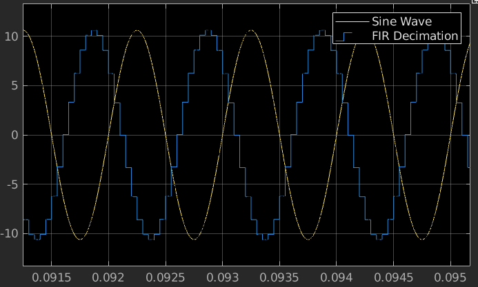
The simulation result below shows the input signal (Sine Wave) and the ADC output (FIR Decimation). The ADC output has the same amplitude as the input and is delayed due to the presence of Decimation filter.

