2-D Geometry Creation at Command Line
Three Elements of Geometry
To describe your geometry through Constructive Solid Geometry (CSG) modeling, use three data structures.
A matrix whose columns describe the basic shapes. When you export geometry from the PDE Modeler app, this matrix has the default name
gd(geometry description).A matrix whose columns contain names for the basic shapes. Pad the columns with zeros or 32 (blanks) so that every column has the same length.
A set of characters describing the unions, intersections, and set differences of the basic shapes that make the geometry.
Basic Shapes
To create basic shapes at the command line, create a matrix whose columns each describe a basic shape. If necessary, add extra zeros to some columns so that all columns have the same length. Write each column using the following encoding.
Circle
| Row | Value |
|---|---|
1 | 1 (indicates a circle) |
2 | x-coordinate of circle center |
3 | y-coordinate of circle center |
4 | Radius (strictly positive) |
Polygon
| Row | Value |
|---|---|
1 | 2 (indicates a polygon) |
2 | Number of line segments n |
3 through 3+n-1 | x-coordinate of edge starting points |
3+n through 2*n+2 | y-coordinate of edge starting points |
Note
Your polygon must not contain any self-intersections.
Rectangle
| Row | Value |
|---|---|
1 | 3 (indicates a rectangle) |
2 | 4 (number of line segments) |
3 through 6 | x-coordinate of edge starting points |
7 through 10 | y-coordinate of edge starting points |
The encoding of a rectangle is the same as that of a polygon, except that the first
row is 3 instead of 2.
Ellipse
| Row | Value |
|---|---|
1 | 4 (indicates an ellipse) |
2 | x-coordinate of ellipse center |
3 | y-coordinate of ellipse center |
4 | First semiaxis length (strictly positive) |
5 | Second semiaxis length (strictly positive) |
6 | Angle in radians from x axis to first semiaxis |
Rectangle with Circular End Cap and Another Circular Excision
Specify a matrix that has a rectangle with a circular end cap and another circular excision.
Create Basic Shapes
First, create a rectangle and two adjoining circles.
rect1 = [3
    4
    -1
    1
    1
    -1
    0
    0
    -0.5
    -0.5];
C1 = [1
    1
    -0.25
    0.25];
C2 = [1
    -1
    -0.25
    0.25];
Append extra zeros to the circles so they have the same number of rows as the rectangle.
C1 = [C1;zeros(length(rect1) - length(C1),1)];
C2 = [C2;zeros(length(rect1) - length(C2),1)];
Combine the shapes into one matrix.
gd = [rect1,C1,C2];
Create Names for the Basic Shapes
In order to create a formula describing the unions and intersections of basic shapes, you need a name for each basic shape. Give the names as a matrix whose columns contain the names of the corresponding columns in the basic shape matrix. Pad the columns with 0 or 32 if necessary so that each has the same length.
One easy way to create the names is by specifying a character array whose rows contain the names, and then taking the transpose. Use the char function to create the array. This function pads the rows as needed so all have the same length. Continuing the example, give names for the three shapes.
ns = char('rect1','C1','C2');
ns = ns';
Set Formula
Obtain the final geometry by writing a set of characters that describes the unions and intersections of basic shapes. Use + for union, * for intersection, - for set difference, and parentheses for grouping. The precedence order, from the highest to the lowest, is as follows: -, *, +. You can control the precedence by using parentheses.
Continuing the example, specify the union of the rectangle and C1, and subtract C2.
sf = '(rect1+C1)-C2';Create Geometry and Remove Face Boundaries
After you have created the basic shapes, given them names, and specified a set formula, create the geometry using decsg. Often, you also remove some or all of the resulting face boundaries. Completing the example, combine the basic shapes using the set formula.
[dl,bt] = decsg(gd,sf,ns);
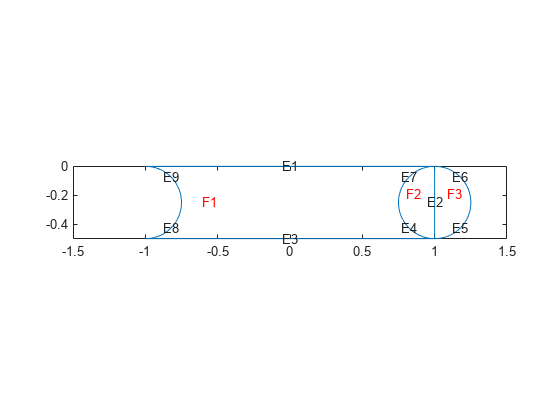
View the geometry with and without boundary removal.
pdegplot(dl,"EdgeLabels","on","FaceLabels","on")
xlim([-1.5,1.5])
axis equal

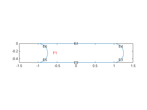
Remove the face boundaries.
[dl2,bt2] = csgdel(dl,bt);
figure
pdegplot(dl2,"EdgeLabels","on","FaceLabels","on")
xlim([-1.5,1.5])
axis equal

Decomposed Geometry Data Structure
The decomposed geometry matrix is encoded according to the following table. Each column of the matrix corresponds to one segment of the decomposed geometry. The matrix uses the minimum number of rows necessary to encode all of the information. For example, if only line segments appear in the decomposed geometry, then the matrix has seven rows. But if there are also circle segments, then the matrix has ten rows, and the last three rows of the columns corresponding to line segments are filled with zeros.
| Row | Circle | Line | Ellipse |
|---|---|---|---|
1 | 1 | 2 | 4 |
2 | Starting x coordinate | Starting x coordinate | Starting x coordinate |
3 | Ending x coordinate | Ending x coordinate | Ending x coordinate |
4 | Starting y coordinate | Starting y coordinate | Starting y coordinate |
5 | Ending y coordinate | Ending y coordinate | Ending y coordinate |
6 | Region label to left of segment, with direction induced by start and
end points (0 is exterior label) | Region label to left of segment, with direction induced by start and
end points (0 is exterior label) | Region label to left of segment, with direction induced by start and
end points (0 is exterior label) |
7 | Region label to right of segment, with direction induced by start and
end points (0 is exterior label) | Region label to right of segment, with direction induced by start and
end points (0 is exterior label) | Region label to right of segment, with direction induced by start and
end points (0 is exterior label) |
8 | x coordinate of circle center | 0 | x coordinate of ellipse center |
9 | y coordinate of circle center | 0 | y coordinate of ellipse center |
10 | Radius | 0 | Length of first semiaxis |
11 | 0 | 0 | Length of second semiaxis |
12 | 0 | 0 | Angle in radians between x axis and first semiaxis |