Electrostatic Analysis of Transformer Bushing Insulator
This example shows how to compute the electric field intensity in a bushing insulator of a transformer. Bushing insulators must withstand large electric fields due to the potential difference between the ground and the high-voltage conductor. This example uses a 3-D electrostatic model to compute the voltage distribution and electric field intensity in the bushing.

Import and plot the bushing geometry.
gmBushing = importGeometry("TransformerBushing.stl");
pdegplot(gmBushing)
Model the surrounding air as a cuboid, and position the cuboid to contain the bushing at its center.
gmAir = multicuboid(1,0.4,0.4);
gmAir.translate([0.25,0.125,-0.07]);
gmModel = addCell(gmAir,gmBushing);
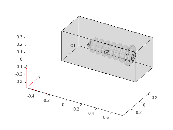
Plot the resulting geometry with the cell labels.
pdegplot(gmModel,CellLabels="on", ...
                 FaceAlpha=0.25)

Create an femodel object for electrostatic analysis and include the geometry in the model.
model = femodel(AnalysisType="electrostatic", ...
                Geometry= gmModel);
Specify the vacuum permittivity value in the SI system of units.
model.VacuumPermittivity = 8.8541878128E-12;
Specify the relative permittivity of the air.
model.MaterialProperties(1) = ...
    materialProperties(RelativePermittivity=1);
Specify the relative permittivity of the bushing insulator.
model.MaterialProperties(2) = ...
    materialProperties(RelativePermittivity=5);
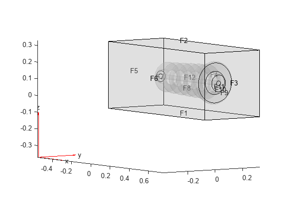
Before specifying boundary conditions, identify the face IDs by plotting the geometry with the face labels. To see the IDs more clearly, rotate the geometry.
pdegplot(gmModel,FaceLabels="on", ...
                 FaceAlpha=0.2)
view([55 5])

Specify the voltage boundary condition on the inner walls of the bushing exposed to conductor.
model.FaceBC(12) = faceBC(Voltage=10E3);
Specify the grounding boundary condition on the surface in contact with the oil tank.
model.FaceBC(9) = faceBC(Voltage=0);
Generate a mesh and solve the model.
model = generateMesh(model,Hmax=0.025);
R = solve(model)
R =
  ElectrostaticResults with properties:

      ElectricPotential: [168795×1 double]
          ElectricField: [1×1 FEStruct]
    ElectricFluxDensity: [1×1 FEStruct]
                   Mesh: [1×1 FEMesh]
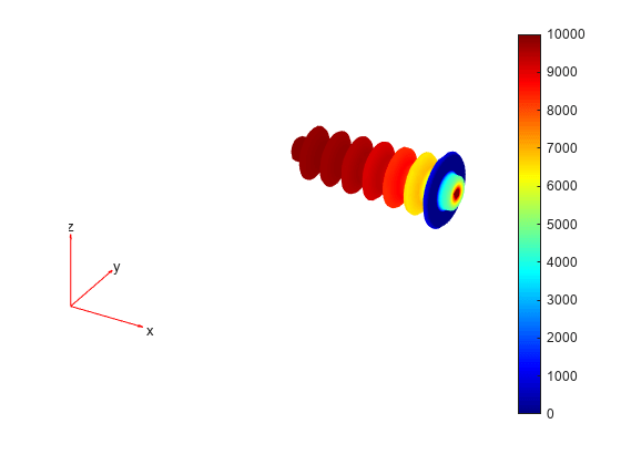
Plot the voltage distribution in the bushing.
elemsBushing = findElements(R.Mesh,"Region",Cell=2);
pdeplot3D(R.Mesh.Nodes, ...
          R.Mesh.Elements(:,elemsBushing), ...
          ColorMapData=R.ElectricPotential);

Plot the magnitude of the electric field intensity in the bushing.
Emag = sqrt(R.ElectricField.Ex.^2 + ...
            R.ElectricField.Ey.^2 + ...
            R.ElectricField.Ez.^2);
pdeplot3D(R.Mesh.Nodes, ...
          R.Mesh.Elements(:,elemsBushing), ...
          ColorMapData=Emag);
