Introduction to Beam Spoiling
Phased array antennas are widely used in modern radar systems. A major benefit of adopting an antenna array is being able to form beams towards desired directions. Because of the size of the aperture, the formed beams are often very narrow, providing a significant gain towards the beam direction. However, depending on the operation mode, narrow beams are not always desirable. For example, in a multifunction phased array radar, the beams may be too narrow to keep the target illuminated long enough to obtain a reliable detection. Another example comes from a weather radar system where the goal is to provide fast weather updates for a region. To do this using default pencil beams, the weather radar needs to move beams extremely fast within the region, which puts a significant requirement on electronics.
One way to address such issue is to transmit a broaden beam, often called a spoiled beam, so it illuminates a larger area [1,2]. Then multiple receiving beams can be formed simultaneously to cover the entire illuminated area to achieve either long target integration time or faster update of a big area.
Beam Spoiling Using Pattern Synthesis Techniques
Since the goal is to produce a broad beam, traditional pattern synthesis techniques can be used. Woodward is a popular algorithm to produce a desired beam pattern for a linear array [3].
Consider a 32-element ULA with half wavelength spacing
N = 32;
c = 3e8;
fc = 10e9;
lambda = freq2wavelen(fc,c);
d = lambda/2;
ant = phased.ULA('NumElements',N,'ElementSpacing',d);
Assume we will steer the array to 30 degrees
ang_st = 30;
antstv = phased.SteeringVector('SensorArray',ant,'PropagationSpeed',c);
w_st = antstv(fc,ang_st);
clf;
pattern(ant,fc,-90:90,0,'CoordinateSystem','rectangular','PropagationSpeed',c,'Type','powerdb','Weights',w_st)
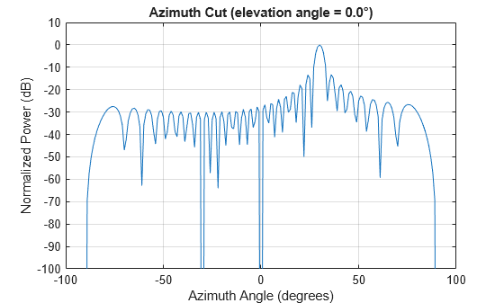
The beamwidth for such a pencil beam can be computed as
bw_pencil = beamwidth(ant,fc,'PropagationSpeed',c,'Weights',w_st)
bw_pencil =
3.6700
To broaden this beam, start by defining the desired pattern. In this example, the desired pattern is just a flag top beam pattern about 10 times wider than the pencil beam. Then using Woodward's approach, the weights that produce the desired pattern can be computed.
ang_pat = -90:90;
mag_pat = zeros(numel(ang_pat),1);
spoil_factor = 10;
broadbeam_min = ang_st-spoil_factor/2*bw_pencil;
broadbeam_max = ang_st+spoil_factor/2*bw_pencil;
mag_pat(ang_pat>=broadbeam_min & ang_pat<=broadbeam_max) = 1;
w_pat_woodward = antstv(fc,ang_pat)'\mag_pat(:);
clf;
pat_woodward = pattern(ant,fc,-90:90,0,'CoordinateSystem','rectangular','PropagationSpeed',c,'Type','powerdb','Weights',w_pat_woodward);
mag_pat_db = mag2db(mag_pat);
mag_pat_db(mag_pat_db<-40) = -40;
plot(ang_pat,[pat_woodward mag_pat_db]);
legend('Woodward','Desired')
ylim([-40 5]);
xlabel('Angles (degrees)');
ylabel('Power (dB)');
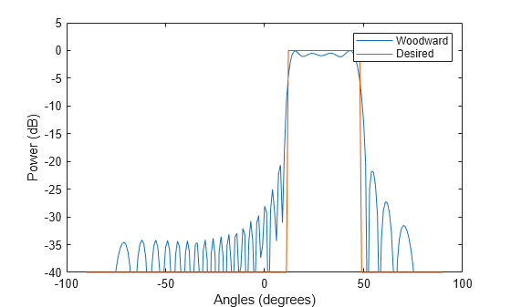
As shown in the figure above, the produced pattern matches the desired pattern well. Compared to the default pencil beam, the sidelobe is also reduced from 13 dB to about 20 dB.
Beam Spoiling Using Phase Only Weights
Woodward algorithm used in the previous section seems to provide a satisfying beam pattern. However, there is a not-so-obvious drawback in the resulting weights. The plot of the resulting weights from Woodward approach looks like
clf;
stem(abs(w_pat_woodward));
xlabel('Element Index');
ylabel('Magnitude');
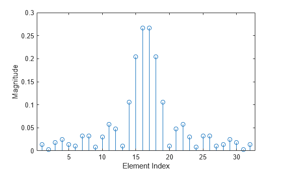
As shown in the figure, the weights include an amplitude taper. This means that not all energy delivered to each element is radiated. Thus, this solution is not very energy efficient. In addition, in a phased array, the amplifiers are often working in the saturated region. Therefore, even if energy efficiency is tolerable, it may not be feasible with the hardware.
To improve energy efficiency, a phase-only weights can be used to spoil the beam [2,4]. Quadratic phase weights is a popular algorithm to achieve this goal [4].
deltak = 2*pi*d/lambda*sind(spoil_factor*bw_pencil/2)/N;
w_pat_quadratic = w_st.*exp(1i*((-(N-1)/2:(N-1)/2).').^2*deltak);
clf;
stem(abs([w_pat_woodward w_pat_quadratic]));
xlabel('Element Index');
ylabel('Magnitude');
legend('Woodward','Quadratic')
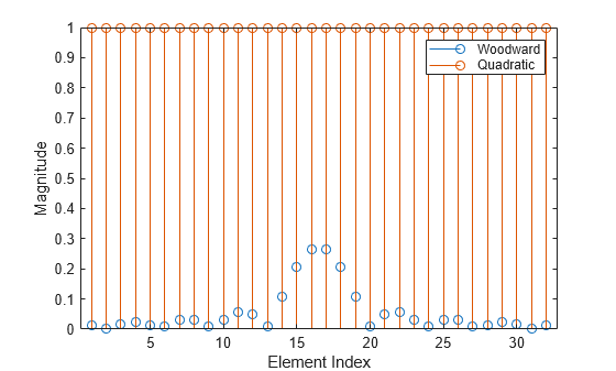
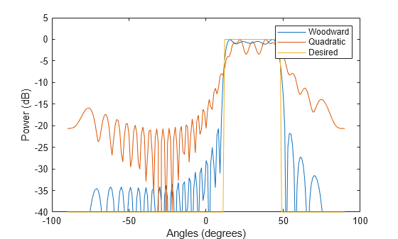
As expected, the quadratic spoiling weights have a constant magnitude. The following figure shows the resulting spoiled beam pattern. It is clear that the phase only weights achieved the same beamwidth compared to the weights that contains both magnitude and phase variations, at a price of higher sidelobe. It is certainly not ideal but there are ways to suppress the sidelobe on the receiving end.
clf;
pat_quadratic = pattern(ant,fc,-90:90,0,'CoordinateSystem','rectangular','PropagationSpeed',c,'Type','powerdb','Weights',w_pat_quadratic);
plot(ang_pat,[pat_woodward pat_quadratic mag_pat_db]);
legend('Woodward','Quadratic','Desired')
ylim([-40 5]);
xlabel('Angles (degrees)');
ylabel('Power (dB)');
Cosecant Square Pattern
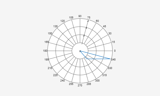
The spoiled pattern shown in the previous is often referred to as a sector beam. In practice, the broadened beam may also form other shapes. For example, an airborne radar system often uses a cosecant square pattern in the elevation direction to illuminate the ground. The reason for such a shape is to control the radiating power, so the beam pattern matches the ground, as shown in the following polar plot, where the cosecant shape is formed between -15 degrees elevation through -50 degrees elevation.
mag_pat_csc = zeros(numel(ang_pat),1);
csc_ang_region_idx = ang_pat>=-50 & ang_pat<=-15;
% compute csc as the reciprocal of sin
mag_pat_csc(csc_ang_region_idx) = 1./abs(sind(ang_pat(csc_ang_region_idx)));

polarpattern(ang_pat,mag_pat_csc);
title('Cosecant radiation pattern')
To achieve the cosecant power pattern, consider an array in the elevation direction.
antel = phased.ULA('NumElements',N,'ElementSpacing',d,'ArrayAxis','z');
antelstv = phased.SteeringVector('SensorArray',antel,'PropagationSpeed',c);
Using Woodward algorithm, the spoiling weights are given by
w_pat_csc_woodward = antelstv(fc,[zeros(size(ang_pat));ang_pat])'\mag_pat_csc(:);
There are also algorithms to compute the phase-only weights to achieve the cosecant power shape [5].
u0 = sind(15);  %design on positive angles so u is positive
u1 = sind(50);
xn = (-(N-1)/2:(N-1)/2)/(N/2);
fun = @(x)(1+0.25*cos(pi*x)).^2;
An1t1 = integral(fun,-1,1);
An1tx = zeros(N,1);
for m = 1:N
    An1tx(m) = integral(fun,-1,xn(m));
end
psi_diff = 2*pi*N*d/2/lambda./(1/u0+(1/u1-1/u0)*An1tx/An1t1);
psi = cumsum(psi_diff)*mean(diff(xn));
w_pat_csc_phase = exp(-1i*psi);  % negative phase to flip to negative elevation
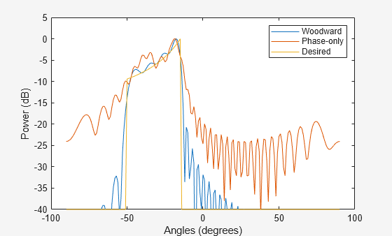
The resulting patterns are shown in the following figure.
pat_csc_woodward = pattern(antel,fc,0,ang_pat,'CoordinateSystem','rectangular','PropagationSpeed',c,'Type','powerdb','Weights',w_pat_csc_woodward);
pat_csc_phase = pattern(antel,fc,0,ang_pat,'CoordinateSystem','rectangular','PropagationSpeed',c,'Type','powerdb','Weights',w_pat_csc_phase);

mag_pat_csc_db = mag2db(mag_pat_csc);
mag_pat_csc_db = mag_pat_csc_db-max(mag_pat_csc_db);
mag_pat_csc_db(mag_pat_csc_db<-40) = -40;

clf;
plot(ang_pat,[pat_csc_woodward pat_csc_phase mag_pat_csc_db]);
legend('Woodward','Phase-only','Desired')
ylim([-40 5]);
xlabel('Angles (degrees)');
ylabel('Power (dB)');
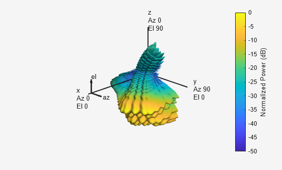
It is easy to extend beam spoiling concept to a rectangular array by combining weights in both azimuth and elevation directions. For example, the following example shows a 32x32 uniform rectangular array that forms a cosecant pattern along elevation and sector beam in azimuth.
antrect = phased.URA('Size',N,'ElementSpacing',d);
w_pat_rect = flipud(w_pat_csc_phase).*w_pat_quadratic.';  % flip cosecant weights to match element indexing
pattern(antrect,fc,-90:90,-90:90,'Type','powerdb','Weights',w_pat_rect(:));
Summary
Beam spoiling is a practical technique used in the field but not discussed in detail in literature. This example shows how to spoil/broaden a beam pattern to form either a sector beam or a cosecant power shaped beam. In addition, the example discussed the tradeoff of achieving the desired beam pattern using weights that have both amplitude and phase vs. a phase only weights. There are certainly other algorithms to form such beams, e.g., using optimization based algorithms [2,6,7].
References
[1] R. Kinsey, Phased Array Beam Spoiling Technique, IEEE Antennas and Propagation Society International Symposium, 1997
[2] G. C. Brown, J. C. Kerce, and M. A. Mitchell, Extreme Beam Broadening using Phase Only Pattern Synthesis, Forth IEEE Workshop on Sensor Array and Multichannel Processing, 2006
[3] Harry L. Van Trees, Optimum Array Processing, Wiley InterSceience, 2002
[4] Mark C. Leifer, Revisiting a Method of Beam Shaping Using Phase Weights, IEEE International Symposium on Phased Array Systems and Technology, 2016
[5] A. Chakraborty, B. N. Das, and G. S. Sanyal, Beam Shaping Using Nonlinear Phase Distribution in a Uniformly Spaced Array, IEEE Transactions on Antennas and Propagation, Vol. AP-30, No. 5, 1982
[6] Lior Maman, Shlomo Zach, and Amir Boag, Phase-only Beam Broadening for Array Antennas, 17th European Conference on Antennas and Propagation, 2023
[7] Prashanth S Shashi Shekhar, Novel Design of Phase Only Cosec Transmit Beam Formation For Phased Array Radars, International Journal of Engineering Research and Technology, Vol 12, No. 12, 2023