Compare Ambiguity Functions for Different Wave Modulation Schemes
This example shows how to visualize and interpret different waveform processing schemes and their tradeoffs in the Pulse Waveform Analyzer app.
Introduction
Radar systems use matched filters in the receiver chain to improve signal-to-noise ratio (SNR). Matched filters are time-reversed and conjugated versions of the transmitted signal. The ambiguity function is the output of a matched filter for a given input waveform. The ambiguity function is used to see a waveform's resolution and ambiguities in both the Doppler and range domains. The ideal ambiguity function is a two-dimensional Dirac delta function, similar to a thumbtack shape, that has no ambiguities. However, this function is unachievable because it requires a waveform with infinite duration and bandwidth. Bandwidth is the difference between the upper and lower frequencies of a waveform. The ambiguity functions of different waveforms provide insight into their advantages and disadvantages.
This example uses the radar system requirements introduced and characterized in the Waveform Analysis Using the Ambiguity Function example and approximates the speed of light to be 3e8 m/s. The desired system has a maximum unambiguous range of 15 km and a range resolution of 1.5 km.
Rectangular Waveforms
Description
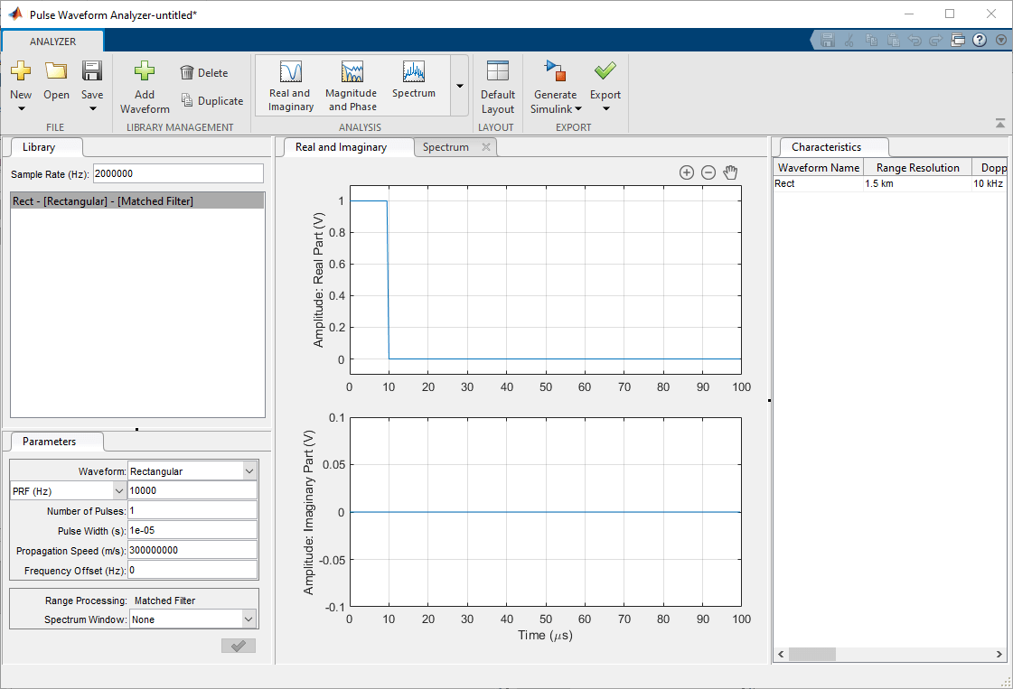
The most basic waveform is the rectangular waveform, whose amplitude alternates between two values, similar to a square wave. The default waveform in the Pulse Waveform Analyzer is a rectangular waveform.
Create a waveform with these parameters:
Name:
RectWaveform:
RectangularSample Rate (Hz):
2 MHzPRF (Hz):
10 kHzPulse Width (s):
10 µs
Use a sample rate that is at least double the highest frequency component of the waveform, which in this case is the bandwidth. In a rectangular waveform, the bandwidth is the reciprocal of the pulse width (10 microseconds). The bandwidth is 100 kHz. Set the sample rate to 2 MHz.

Range and Resolution
The Characteristics tab shows the properties of a radar system that uses a given rectangular waveform. To observe the relationship between the pulse repetition frequency (PRF) and other characteristics, increase and decrease the PRF values.
Duplicate the rectangular waveform twice, and change their PRFs to
5kHz and20kHz.
The Characteristics tab shows that the PRF is inversely proportional to the maximum unambiguous range because the maximum unambiguous range is determined by the amount of time between pulses. The relationship between PRF and maximum unambiguous range applies for all pulsed waveforms, as the farther apart the pulses are spread, the farther the signal can propagate and return before the next pulse is emitted.
Beyond simply measuring range, radar systems measure velocity by using the Doppler effect. The greater the Doppler shift is compared to the original signal, the faster the target is moving. As such, Doppler shift and speed are directly proportional and are often used interchangeably. The Characteristics tab displays Doppler resolution and maximum Doppler shift, which correspond to the speed resolution and the maximum detectable speed, respectively. These waveforms also demonstrate the Doppler Dilemma, where a small PRF gives a larger maximum unambiguous range but poor maximum Doppler while a larger PRF gives better maximum Doppler but worse maximum unambiguous range.
Change the PRF for each waveform back to
10kHz and change the pulse width of the duplicate waves to20and30µs.
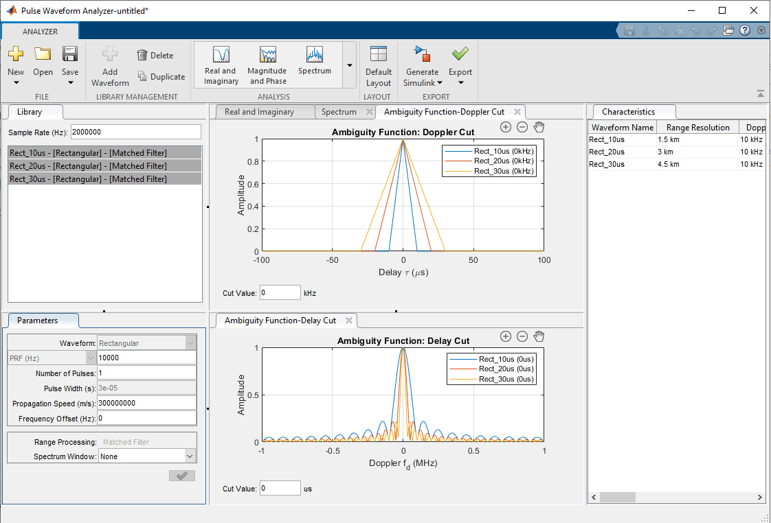
The Characteristics tab shows that smaller pulse widths give better range resolution and a smaller minimum range. The tradeoff for a smaller pulse width is that it requires a higher peak power for the return echo to be detected reliably.
The original waveform has a maximum range of 15 km and a range resolution of 1.5 km, but its Doppler resolution is 10 kHz. Assuming that the radar is operating at 1 GHz, the Doppler resolution dictates that the radar system cannot separate targets with a speed difference smaller than 30 km/s, which is far too large to be practical for many real-world radar systems. To further visualize the range and Doppler domains, view the different ambiguity plots.
Click on the Analysis drop-down menu and, under the Ambiguity Plots section, add the
Contour,Surface,Delay Cut, andDoppler Cutplots.

The Doppler Cut graph at 0 kHz shows the autocorrelation function (ACF) of the waveform, which corresponds to the matched filter response of a stationary target. The first null response for each waveform is the same as its respective pulse width. To obtain the range resolution, multiply the pulse width by the speed of light over 2 to account for the round trip. For the example waveforms, the range resolutions are 1.5 km, 3 km, and 4.5 km.
The zero-delay cut plot shows large gaps until the first null response for each of the waveforms. Looking at the 10 µs pulse width waveform, the first null is at 0.1 MHz, which translates to a Doppler shift of 100 kHz or 30 km/s. In other words, two targets must have speeds that differ by over 30 km/s to be separated via Doppler response, which is unrealistic in most radar situations.

The Contour plot displays the nonzero response of the ambiguity function. Because the duty cycle, or the ratio of the pulse width to the pulse period, is 10%, the nonzero response only occupies about 10% of all delays. The surface ambiguity function shows the response in relation to both delay and Doppler, which is simply another way to visualize the 3-D contour plot.
The changes in the pulse width and the PRF show how to improve maximum ambiguous range and range resolution, but the Doppler resolution remains poor. The solution is to use a smaller pulse width with a larger PRF, but both changes greatly reduce the maximum power and thus the SNR, making it more difficult to detect objects. The product of the bandwidth and the pulse length is called the time-bandwidth product, and since the bandwidth and the pulse length of a rectangular wavelength are inversely proportional, the time-bandwidth product cannot exceed 1 for this waveform. Because of these tradeoffs, rectangular waveforms are rarely used in practical radar systems.
Linear FM
Description
Linear frequency modulated (FM) waveforms are phase-modulated waveforms whose frequency either increases or decreases linearly throughout the duration of the pulse. Linear FM waveforms are a popular choice for radar systems because, unlike in rectangular waveforms, the pulse width and the energy of the pulse are decoupled due to the changing frequency. This decoupling makes the time-bandwidth product exceed 1 and allows for improved target detection ability. The Pulse Waveform Analyzer app has the functionality to model these waveforms as well. For more information on linear FM waveforms, view Linear Frequency Modulated Pulse Waveforms
Create a waveform with these parameters:
Name:
LFM1Waveform:
Linear FMSample Rate (Hz):
200 kHzPRF (Hz):
10 kHzPulse Width (s):
50 µsSweep Bandwidth (Hz):
100 kHz
Click on the Spectrum tab to view the peak power.

Range and Resolution
Since the waveform is longer, the power is increased. However, the range resolution, the Doppler resolution, and the maximum unambiguous range are the same as for the rectangular waveform due to the effects of the frequency modulation. The Characteristics tab shows that the minimum range is greatly increased, meaning that the system cannot detect any objects that are closer than 7.5 km. To improve the Doppler resolution and decrease the minimum range, use numerous pulses.
Decrease the pulse width to
10µs and increase the number of pulses to5.
By using a coherent pulse train and Doppler processing, the Doppler resolution improves in proportion to the number of pulses added. The Characteristics tab shows that range resolution, maximum Doppler, and maximum unambiguous range still remain the same, but the Doppler resolution is much improved. The tradeoff for adding more pulses is that sidelobes are now present, which can be seen in the Matched Filter Response tab. One way to reduce these sidelobes is to apply a window.
Duplicate the linear FM waveform, and in the copied waveform, change the Spectrum Window from
NonetoHannand set the Spectrum Range from0to200kHz.

Press Ctrl and click on the two waveforms to compare them side by side. The window decreases the mainlobe's power from 100 V to less than 50 V, which is a loss of around 33 dB in power, and the width of the mainlobe is also wider compared to the waveform where you did not apply a window. However, the window does flatten the sidelobes, which makes detection using thresholding more reliable.
Frequency Modulated Continuous Waveforms (FMCW)
Description
Frequency Modulated Continuous Waveforms (FMCW) are similar to linear FM waveforms but are continuous rather than pulsed, which is effectively a linear FM waveform but with a duty cycle of 100%. FMCWs are often used in short-range automotive radar systems due to their sharp resolution for both Doppler and range.
Create a waveform with these parameters:
Name:
FMCWWaveform:
FMCWSample Rate (Hz):
200 kHzSweep Time (s):
100 µsSweep Bandwidth (Hz):
500 kHzNumber of Sweeps:
1
Range and Resolution
Check the Characteristics tab and see that most of the characteristics are the same as for the rectangular waveform. One notable difference is that with continuous waveforms, the receiver always remains on, so the minimum range is always 0. To improve the range resolution, increase the sweep bandwidth.
Increase the sweep bandwidth to
500kHz.
The range resolution improves by a factor of 5 to 0.3 km. However, the Doppler resolution is still poor at 10 kHz. One way to improve this is by increasing the sweep time, which essentially lengthens the duration of the frequency modulation.
Increase the sweep time from
0.1ms to1ms.
The increased sweep time improves the Doppler resolution by a factor of 10, reducing it to 1 kHz. Although the Doppler resolution improves, the tradeoff for lengthening the signal is that the maximum Doppler decreases by the same factor, so if there are fast moving targets that exceed this Doppler limit, the radar system is unable to determine their speed without additional processing complexity.
Revert the sweep time back to
0.1ms and now change the number of sweeps to10from1.
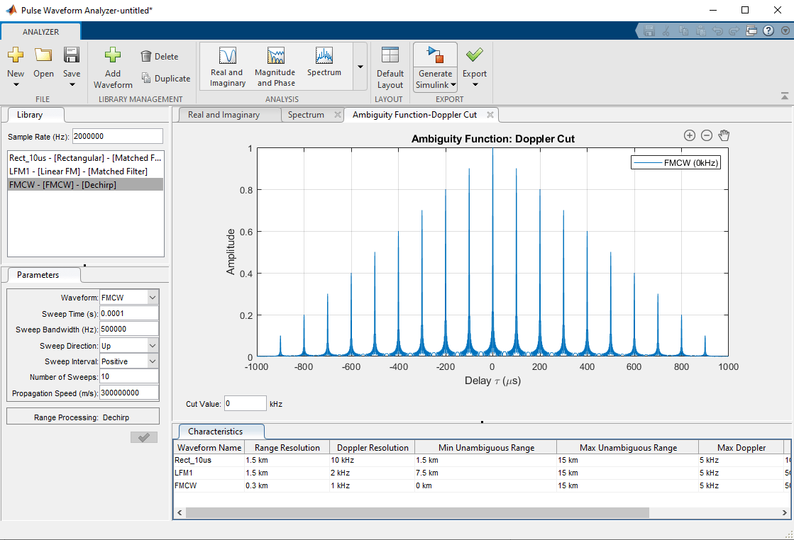
Increasing the number of sweeps follows the same principle of coherent pulse trains to improve the Doppler resolution from 10 kHz to 1 kHz. The Doppler Cut tab displays the ambiguity function, which has sizable sidelobes.

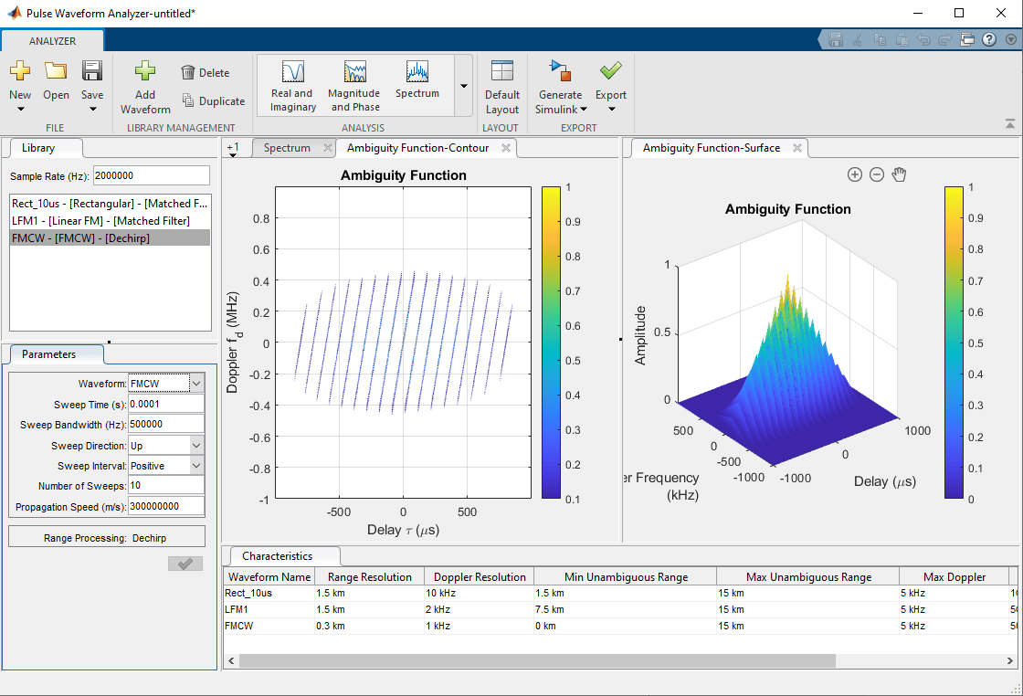
An ambiguity function that has numerous sidelobes is often referred to as a "bed of nails" ambiguity function. To get a better look, compare the 3-D ambiguity plots side by side.

The ambiguity function is slightly skewed along the Doppler-Delay plane, which shows that slight changes in Doppler can cause errors in range measurements. This phenomenon is called range-Doppler coupling and occurs commonly in linear FM waveforms.
Another tradeoff with the FMCW waveform is that the maximum unambiguous range is a function of the sweep time, which can be difficult to increase past a certain point. Thus, many FMCW radars are limited to a short range, but because of their improved range and Doppler resolution compared to other waveforms, FMCW waveforms are usually used in systems that require high measurement accuracy.
Summary
This example shows how to use the Pulse Waveform Analyzer app to compare different types of waveforms, including rectangular, linear FM, and FMCW waveforms. The ambiguity function of a waveform is the output of a matched filter with the waveform as input, and the ambiguity function serves as a valuable tool for determining the effectiveness of a waveform for a given radar system.