Simulating Test Signals for a Radar Receiver in Simulink
This example shows how to model an end-to-end monostatic radar using Simulink®. A monostatic radar consists of a transmitter colocated with a receiver. The transmitter generates a pulse which hits the target and produces an echo received by the receiver. By measuring the time location of the echoes, you can estimate the range of the target. The first part of this example demonstrates how to detect the range of a single target using the equivalent of a single element antenna. The second part of the example will show how to build a monostatic radar with a 4-element uniform linear array (ULA) that detects the range of 4 targets.
Available Example Implementations
This example includes two Simulink® models:
Monostatic Radar with One Target: slexMonostaticRadarExample.slx
Monostatic ULA Radar with Four Targets: slexMonostaticRadarMultipleTargetsExample.slx
Monostatic Radar with One Target
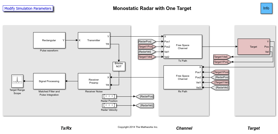
This model simulates a simple end-to-end monostatic radar. Using the transmitter block without the narrowband transmit array block is equivalent to modeling a single isotropic antenna element. Rectangular pulses are amplified by the transmitter block then propagated to and from a target in free-space. Noise and amplification are then applied in the receiver preamp block to the return signal, followed by a matched filter. Range losses are compensated for and the pulses are noncoherently integrated. Most of the design specifications are derived from the Simulating Test Signals for a Radar Receiver example provided for System objects.

The model consists of a transceiver, a channel, and a target. The blocks that corresponds to each section of the model are:
Transceiver
Rectangular- Creates rectangular pulses.Transmitter- Amplifies the pulses and sends a Transmit/Receive status to theReceiver Preampblock to indicate if it is transmitting.Receiver Preamp- Receives the pulses from free space when the transmitter is off. This block also adds noise to the signal.Constant- Used to set the position and velocity of the radar. Their values are received by theFreespaceblocks using theGotoandFrom.Signal Processing- Subsystem performs match filtering and pulse integration.Target Range Scope- Displays the integrated pulse as a function of the range.
Signal Processing Subsystem

Matched Filter- Performs match filtering to improve SNR.TVG- Time varying gain to compensate for range loss.Pulse Integrator- Integrates several pulses noncoherently.
Channel
Freespace- Applies propagation delays, losses and Doppler shifts to the pulses. One block is used for the transmitted pulses and another one for the reflected pulses. TheFreespaceblocks require the positions and velocities of the radar and the target. Those are supplied using theGotoandFromblocks.
Target
Target- Subsystem reflects the pulses according to the specified RCS. This subsystem includes aPlatformblock that models the speed and position of the target which are supplied to theFreespaceblocks using theGotoandFromblocks. In this example the target is stationary and positioned 1998 meters from the radar.
Exploring the Example
Several dialog parameters of the model are calculated by the helper function helperslexMonostaticRadarParam. To open the function from the model, click on Modify Simulation Parameters block. This function is executed once when the model is loaded. It exports to the workspace a structure whose fields are referenced by the dialogs. To modify any parameters, either change the values in the structure at the command prompt or edit the helper function and rerun it to update the parameter structure.
Results and Displays
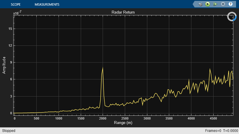
The figure below shows the range of the target. Target range is computed from the round-trip delay of the reflected pulse. The delay is measured from the peak of the matched filter output. We can see that the target is approximately 2000 meters from the radar. This range is within the radar's 50-meter range resolution from the actual range.

Monostatic Radar with Multiple Targets
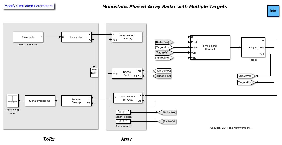
This model estimates the range of four stationary targets using a monostatic radar. The radar transceiver uses a 4-element uniform linear antenna array (ULA) for improved directionality and gain. A beamformer is also included in the receiver. The targets are positioned at 1988, 3532, 3845 and 1045 meters from the radar.

The blocks added to the previous example are:
Narrowband Tx Array- Models an antenna array for transmitting narrowband signals. The antenna array is configured using the "Sensor Array" tab of the block's dialog box. TheNarrowband Tx Arrayblock models the transmission of the pulses through the antenna array in the four directions specified using theAngport. The output of this block is a matrix of four columns. Each column corresponds to the pulses propagated towards the directions of the four targets.

Narrowband Rx Array- Models an antenna array for receiving narrowband signals. The array is configured using the "Sensor Array" tab of the block's dialog box. The block receives pulses from the four directions specified using theAngport. The input of this block is a matrix of four columns. Each column corresponds to the pulses propagated from the direction of each target. The output of the block is a matrix of 4 columns. Each column corresponds to the signal received at each antenna element.
Range Angle- Calculates the angles between the radar and the targets. The angles are used by theNarrowband Tx Arrayand theNarrowband Rx Arrayblocks to determine in which directions to model the pulses' transmission or reception.
Phase Shift Beamformer- Beamforms the output of theReceiver Preamp. The input to the beamformer is a matrix of 4 columns, one column for the signal received at each antenna element. The output is a beamformed vector of the received signal.
This example illustrates how to use single Platform, Freespace and Target blocks to model all four round-trip propagation paths. In the Platform block, the initial positions and velocity parameters are specified as three-by-four matrices. Each matrix column corresponds to a different target. Position and velocity inputs to the Freespace block come from the outputs of the Platform block as three-by-four matrices. Again, each matrix column corresponds to a different target. The signal inputs and outputs of the Freespace block have four columns, one column for the propagation path to each target. The Freespace block has two-way propagation setting enabled. The "Mean radar cross section" (RCS) parameter of the Target block is specified as a vector of four elements representing the RCS of each target.
Exploring the Example
Several dialog parameters of the model are calculated by the helper function helperslexMonostaticRadarMultipleTargetsParam. To open the function from the model, click on Modify Simulation Parameters block. This function is executed once when the model is loaded. It exports to the workspace a structure whose fields are referenced by the dialogs. To modify any parameters, either change the values in the structure at the command prompt or edit the helper function and rerun it to update the parameter structure.
Results and Displays
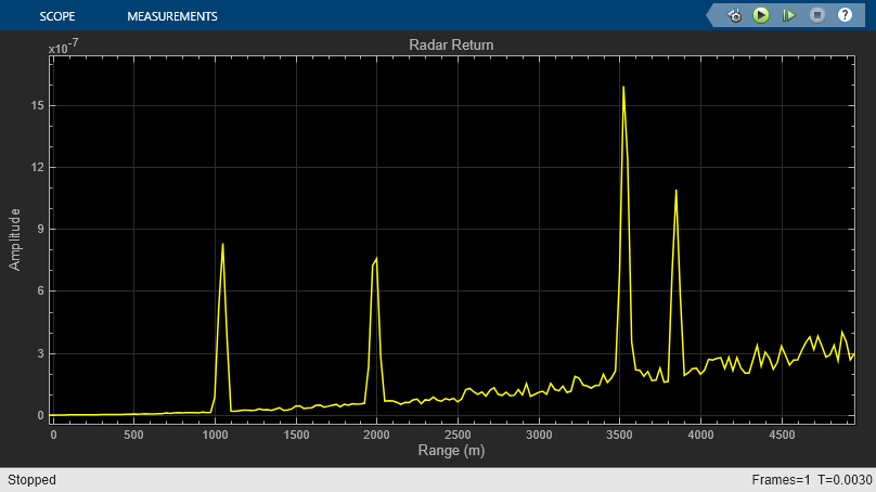
The figure below shows the detected ranges of the targets. Target ranges are computed from the round-trip time delay of the reflected signals from the targets. We can see that the targets are approximately 2000, 3550, and 3850 meters from the radar. These results are within the radar's 50-meter range resolution from the actual range.
