Integrated Sensing and Communication I:Radar-Centric Approach Using PMCW Waveform
This example shows how to model a radar-centric Integrated Sensing and Communication (ISAC) system based on a MIMO radar transmitting a PMCW waveform. Part II of this example shows how to model a communication-centric ISAC system based on a generic MIMO-OFDM communication system.
Introduction
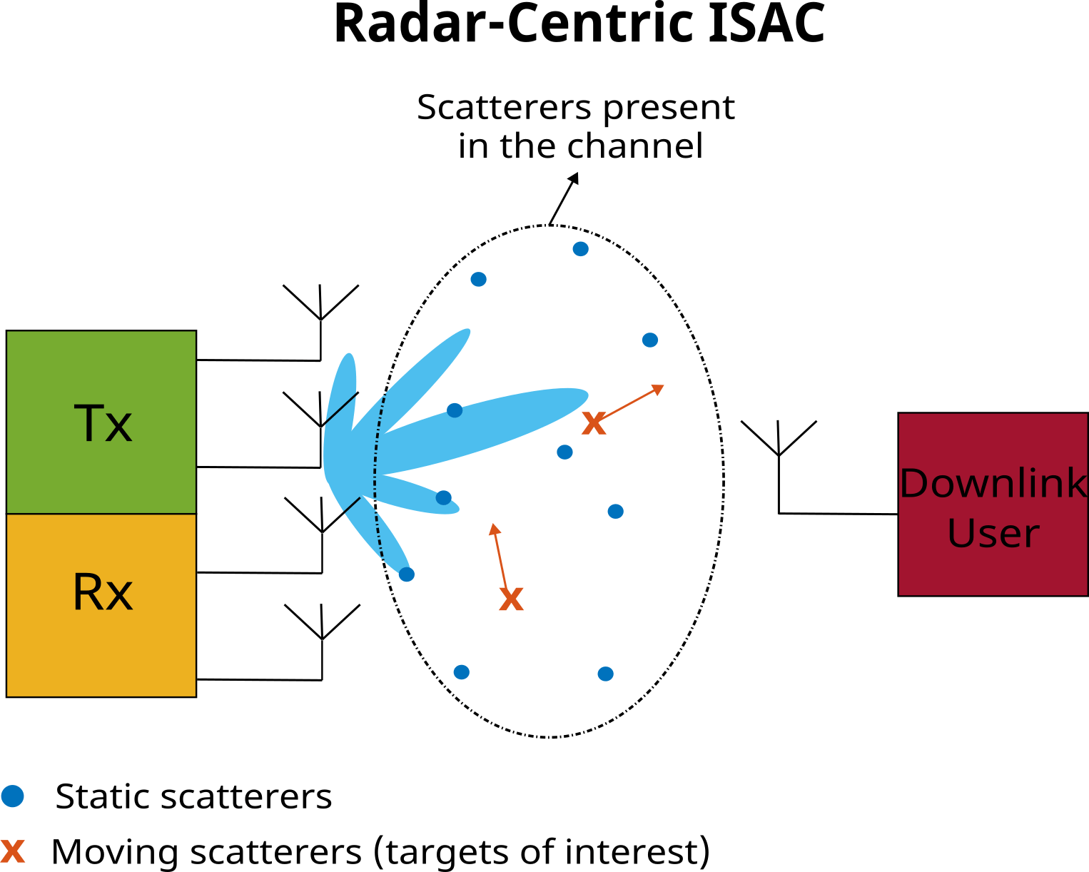
ISAC systems represent a pivotal strategy devised to address challenges posed by the increasingly congested frequency spectrum and the escalating demand for large bandwidth by radar and communication systems. In an ISAC framework, both radar and communication functionalities are integrated to share the same hardware infrastructure, utilizing a common transmit waveform. This example shows how communication capabilities can be added to a MIMO (Multiple Input Multiple Output) radar system that transmits a phase-modulated continuous wave (PMCW) waveform. Given that the communication functionality is embedded within the radar system, this ISAC method is characterized as a radar-centric.
This example considers a scenario when an ISAC system is implemented using a monostatic radar. The primary goal of the radar is to detect and estimate parameters of the targets in its field of view. The goal of the communication function added to the radar is to deliver a data payload to a downlink user.
System parameters
Consider a radar system operating at a carrier frequency of 77 GHz with a bandwidth of 150 MHz.
% Set the random number generator for reproducibility
rng('default');

carrierFrequency = 77e9;                                                % Carrier frequency (Hz)
waveLength = freq2wavelen(carrierFrequency);                            % Wavelength
bandwidth = 150e6;                                                      % Bandwidth (Hz)
sampleRate = bandwidth;                                                 % Assume the sample rate is equal to the bandwidth
Create a transmitter assuming the peak transmit power is 1 W.
peakPower = 1;                                                          % Peak power (W)
transmitter = phased.Transmitter('PeakPower', peakPower, 'Gain', 0);
Create a radar receiver and set the noise figure to 3 dB and the reference noise temperature to 290 K.
noiseFigure = 3.0;                                                      % Noise figure (dB)
referenceTemperature = 1;                                               % Reference temperature (K)
radarReceiver = phased.Receiver('SampleRate', sampleRate, 'NoiseFigure', noiseFigure,...
     'ReferenceTemperature', referenceTemperature, 'AddInputNoise', true,...
     'InputNoiseTemperature', referenceTemperature, 'Gain', 0);
Let the transmitter have a uniform linear array (ULA) of four isotropic antennas spaced at half a wavelength apart.
Ntx = 4;                                                                % Number of transmit antenna elements
element = phased.IsotropicAntennaElement('BackBaffled', true);
txArray = phased.ULA(Ntx, waveLength/2, 'Element', element);
Let the radar receiver also have a ULA of four isotropic elements that are spaced Ntx*waveLength/2 meters apart. Such spacing is required to create a largest possible virtual aperture for the MIMO radar without causing grating lobes.
Nrx = 4;                                                                % Number of receive antenna elements at the radar receiver
rxArray = phased.ULA(Nrx,Ntx*waveLength/2, 'Element', element);
Create a downlink user receiver and set the noise figure to 3.3 dB and the reference noise temperature to 290 K.
downlinkNoiseFigure = 3.3;                                              % Noise figure at the downlink receiver (dB)
downlinkReferenceTemperature = 290;                                     % Reference temperature at the downlink receiver (dB)
downlinkReceiver = phased.Receiver('SampleRate', sampleRate, 'NoiseFigure', downlinkNoiseFigure,...
    'ReferenceTemperature', downlinkReferenceTemperature, 'AddInputNoise', true,...
    'InputNoiseTemperature', downlinkReferenceTemperature, 'Gain', 0);
Let the downlink user have a single omnidirectional antenna.
downlinkAntenna = phased.IsotropicAntennaElement;
ISAC Scenario
Let the radar transmitter and receiver be located at the origin. Point the transmit and the receive array normals along the x-axis.
radarPosition = [0; 0; 0];                                              % Location of the transmitter (m)
radarOrientationAxis = eye(3);                                          % Tx array orientation
Set the downlink user position to be some distance away from the radar transmitter.
userPosition = [80; 60; 0]; % Location of the receiver (m)This example assumes that the transmitter, the radar receiver, and the downlink receiver are static.
The environment encompassing the area between the transmitter and the downlink receiver is populated with scatterers. These scatterers can be static or they can be moving. Within the context of the sensing function, the scatterers present in the communication channel, regardless of their state of motion, are considered as radar targets.
Let the three moving scatterers be the targets of interest.
targetPositions = [60 70 90;                                            % Target positions (m)
                   -25 15 30;
                   0 0 0];

targetVelocities = [-15 20 0;                                           % Target velocities (m/s)
                    12 -10 25;
                    0 0 0];

% Platform to model target motion
targetMotion = phased.Platform('InitialPosition', targetPositions, 'Velocity', targetVelocities);

% The values of the reflection coefficients are chosen on random
targetReflectionCoefficients = randn(1, size(targetPositions, 2)) + 1i*randn(1, size(targetPositions, 2));
Since this example simulates a monostatic radar, it is convenient to know the values of the range, azimuth, and radial velocity for the targets of interest.
[targetAzimuth, ~, targetRange] = cart2sph(targetPositions(1, :), targetPositions(2, :), targetPositions(3, :));
targetAzimuth = rad2deg(targetAzimuth);
targetRadialVelocity = sum(targetVelocities.*(targetPositions./vecnorm(targetPositions)));

for i = 1:size(targetPositions, 2)
    fprintf("Target %d: range=%.2f (m), azimuth=%.2f (deg), radial velocity = %.2f\n", i,...
        targetRange(i), targetAzimuth(i), targetRadialVelocity(i));
end
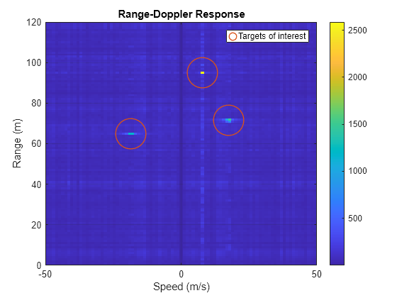
Target 1: range=65.00 (m), azimuth=-22.62 (deg), radial velocity = -18.46
Target 2: range=71.59 (m), azimuth=12.09 (deg), radial velocity = 17.46
Target 3: range=94.87 (m), azimuth=18.43 (deg), radial velocity = 7.91
The rest of the scatterers in the scene are static. Use helperGenerateStaticScatterers helper function to generate positions of the static scatterers within some region of interest.
regionOfInterest = [0 120; -80 80];                                     % Bounds of the region of interest
numScatterers = 200;                                                    % Number of scatterers distributed within the region of interest
[scattererPositions, scattererReflectionCoefficients] = helperGenerateStaticScatterers(numScatterers, regionOfInterest);
Use two separate phased.ScatteringMIMOChannel objects to model the propagation channels between the transmitter and the radar receiver, and between the transmitter and the downlink user.
radarChannel = phased.ScatteringMIMOChannel('CarrierFrequency', carrierFrequency, 'TransmitArray', txArray,...
    'TransmitArrayPosition', radarPosition, 'ReceiveArray', rxArray, 'ReceiveArrayPosition', radarPosition,...
    'TransmitArrayOrientationAxes', radarOrientationAxis, 'ReceiveArrayOrientationAxes', radarOrientationAxis,...
    'SampleRate', sampleRate, 'SimulateDirectPath', false, 'ScattererSpecificationSource', 'Input Port');

commChannel = phased.ScatteringMIMOChannel('CarrierFrequency', carrierFrequency, 'TransmitArray', txArray,...
    'TransmitArrayPosition', radarPosition, 'ReceiveArray', downlinkAntenna, 'ReceiveArrayPosition', userPosition,...
    'TransmitArrayOrientationAxes', radarOrientationAxis, 'SampleRate', sampleRate,...
    'SimulateDirectPath', true, 'ScattererSpecificationSource', 'Input Port');
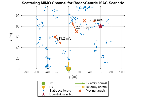
Visualize the channels using helperVisualizeScatteringMIMOChannel helper function.
helperVisualizeScatteringMIMOChannel(radarChannel, scattererPositions, targetPositions, targetVelocities)
plot(userPosition(2), userPosition(1), 'pentagram', 'DisplayName', 'Downlink user Rx', 'MarkerSize', 16,...
    'Color', '#A2142F', 'MarkerFaceColor', '#A2142F')
title('Scattering MIMO Channel for Radar-Centric ISAC Scenario');
Signaling Scheme
A PMCW radar repeatedly transmits a selected phase-coded sequence. The duration of the transmitted sequence is called a modulation period. Since the duty cycle of a PMCW radar is equal to one, the next modulation period starts right after the previous. This example uses a maximum length pseudo-random binary sequence (PRBS) also frequently referred to as an m-sequence. Maximum length sequences have low autocorrelation sidelobes that result in a good range estimation performance.
Create a 255 chips long PRBS.
Nchip = 255;                                                            % Length of the PRBS
prbs = mlseq(Nchip);                                                    % Maximum length sequence
Given that the chip duration of a phase-modulated waveform is an inverse of the total bandwidth, compute the modulation period.
chipWidth = 1/bandwidth;                                                % Chip duration
modulationPeriod = Nchip * chipWidth;                                   % Modulation period
The modulation period determines the maximum unambiguous range of the radar, that is to unambiguously measure a target's range the echo from the target needs to come back before a modulation period is over.
fprintf("Maximum unambiguous range: %.2f (m).\n", time2range(modulationPeriod));Maximum unambiguous range: 254.82 (m).
In order to implement a MIMO radar, each transmit antenna must transmit an orthogonal sequence. One way to achieve orthogonality is to use different orthogonal sequences for each antenna. This approach is expensive as it requires as many different correlators at the receiver as there are transmit antennas. Additionally, in practice it might be hard to achieve good range sidelobes and good crosscorrelation properties for all time delays of interest and all transmitted waveforms.
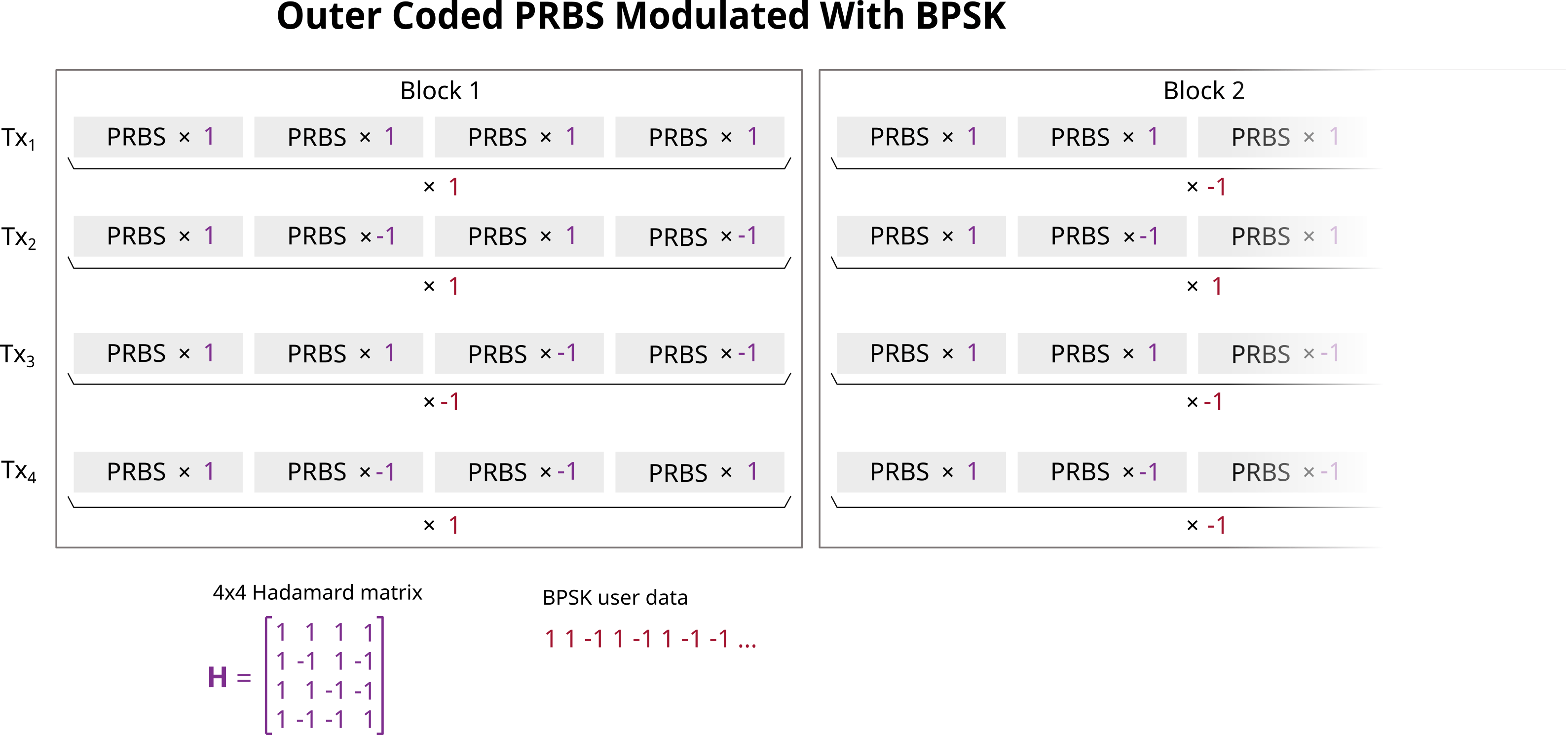
Another approach is to use outer codes. This example uses the Hadamard code for outer coding. Let H be an Ntx*Ntx Hadamard matrix. Each antenna transmits the same PRBS Ntx times, but each repetition of the sequence is multiplied by a corresponding entry in H. Specifically, the columns of H correspond to the transmit antennas, and the rows correspond to the repetitions of the PRBS. To separate echoes from each transmitter at each receive antenna, the Ntx received repetitions of the transmitted sequence are multiplied by the corresponding values in the Hadamard code matrix H and then summed together.
Use the hadamard function to generate a matrix of Hadamard outer codes and create an outer coded transmit sequences for each antenna.
H = hadamard(Ntx);
outterCodedPRBS = kron(H, prbs);
Compute the duration and the length of an outer coded PRBS.
blockDuration = modulationPeriod * Ntx;
blockLength = Nchip * Ntx;
A set of outer coded PRBS transmitted by each transmit antenna constitutes a single transmit block. Each such block can carry Ntx bits of user data - one bit per transmit antenna. This is achieved by multiplying sequences transmitted by each antenna by a corresponding BPSK symbol as shown on the following diagram.
Received Signal Simulation
Simulate transmission of total 256 outer coded blocks.
Nb = 256; % Total number of transmitted blocksSince the targets are moving, the communication channel between the transmitter and the downlink user is going to be time varying. To account for this variation a fresh estimate of the channel matrix must be obtained at regular intervals. In this example, the channel sounding is performed by transmitting an unmodulated outer coded PRBS. Assuming that the downlink user has a full knowledge of the transmitted sequence, the channel estimate can be obtained on the receive side using the standard channel estimation approaches such as zero forcing.
Perform channel sounding every M blocks.
M = 32;                                                                 % Perform sounding every Mth block
numSoundBlocks = numel(1:M:Nb);                                         % Total number of sounding blocks
fprintf("Channel matrix update period: %.2f (ms).\n", blockDuration*M*1e3);
Channel matrix update period: 0.22 (ms).
Preallocate space to store transmitted data.
txDataBin = ones(Nb-numSoundBlocks, Ntx);
txDataBpsk = ones(Nb, Ntx);
Preallocate space for signals received at the radar receiver and the downlink user receiver.
radarRxSignal = zeros(blockLength, Nrx, Nb);
commRxSignal = zeros(blockLength, Nb + 1);
Transmit one block at a time. Propagate it through the radar and the communication channels and store the signals received at the radar and the downlink receivers.
it = 0;
for i = 1:Nb
    if mod(i - 1, M) == 0   % Communication channel sounding
        % Transmit the outer codded PRBS without any data added to it
        pmcwSignal = outterCodedPRBS;
    else                    % Data transmission
        % Generate binary payload and peform BPSK modulation
        it = it + 1;
        txDataBin(it, :) = randi([0 1], [1 Ntx]);
        txDataBpsk(i, :) = pskmod(txDataBin(it, :), 2);

        % Modulate the outer coded PRBS with the BPSK data payload
        pmcwSignal = outterCodedPRBS .* txDataBpsk(i, :);
    end

    % Transmit signal
    txSignal = transmitter(pmcwSignal);

    % Update target positions
    [targetPositions, targetVelocities] = targetMotion(blockDuration);

    % Simulate signal propagation through the radar channel - from
    % transmitter to the scatterers and back to the radar receiver
    radarChannelSignal = radarChannel(txSignal, [scattererPositions targetPositions],...
        [zeros(size(scattererPositions)) targetVelocities],...
        [scattererReflectionCoefficients targetReflectionCoefficients]);

    % Simulate signal propagation through the comm channel - from
    % transmitter to the scatterers and to the downlink user
    commChannelSignal = commChannel(txSignal, [scattererPositions targetPositions],...
        [zeros(size(scattererPositions)) targetVelocities],...
        [scattererReflectionCoefficients targetReflectionCoefficients]);

    % Add thermal noise at the receiver
    radarRxSignal(:, :, i) = radarReceiver(radarChannelSignal);
    commRxSignal(:, i) = downlinkReceiver(commChannelSignal);
end
After Nb iterations, due to the channel delay between the transmitter and the downlink user, a portion of the last transmitted block remains in the channel buffer. To fully receive the last transmitted symbol flush the communication channel buffer.
commChannelSignal = commChannel(zeros(size(txSignal)), [scattererPositions targetPositions],...
    [zeros(size(scattererPositions)) targetVelocities],...
    [scattererReflectionCoefficients targetReflectionCoefficients]);

commRxSignal(:, end) = downlinkReceiver(commChannelSignal);
Received Signal Processing
At Radar Receiver
The dimensions of the received base band signal at the radar receiver are Nchip*Ntx-by-Nrx-by-Nb. Here, the first dimension is the fast-time dimension. It has a length of Nchip*Ntx corresponding to the Nchip long PRBS repeated Ntx times to implement the outer coding. The second dimension is the spatial dimension of length Nrx equal to the number of receive antennas. Finally, the third dimension is the slow-time dimension of length Nb equal to the number of transmitted blocks.
The following diagram shows the signal processing steps at the radar receiver.

The first step is to separate signals transmitted by different transmit antennas at each receiver. Use helperDecodeMIMOPMCW helper function to decode the outer coded received sequences.
radarRxSignalDecoded = helperDecodeMIMOPMCW(radarRxSignal, H);
The dimension of the signal after decoding is Nchip-by-Ntx-by-Nrx-by-Nb. The next step is to remove the data payload. This is accomplished by multiplying the received signals with the corresponding transmitted BPSK symbols.
for i = 1:Nb
    radarRxSignalDecoded(:, :, :, i) = radarRxSignalDecoded(:, :, :, i) .* txDataBpsk(i, :);
end
Once the communication data has been removed, form a radar data cube such that the channel dimension corresponds to a virtual array of Ntx*Nrx elements created by convolving the transmit and the receive array apertures.
radarDataCube = reshape(radarRxSignalDecoded, Nchip, Ntx*Nrx, Nb);
Perform matched filtering in the frequency domain.
prbsDFT = fft(prbs);
Z = fft(radarDataCube) .* conj(prbsDFT);
This example models a scenario with a very large number of radar targets. However, not all of the observed targets are targets of interest. If the targets of interest are the moving scatterers, the static scatterers can be filtered out in the Doppler domain since the Doppler shift from a static scatterer is equal to zero. Perform FFT over the slow-time dimension and zero out the DC component to remove static scatterers.
Y = fft(Z, [], 3);
Y(:, :, 1) = 0;
y = ifft(Y, Nb, 3);
To perform range-angle processing, first use helperVirtualArray helper function to combine the transmit and the receive arrays into a MIMO virtual array. After that compute the range-angle response.
virtualArray = helperVirtualArray(txArray, rxArray);
rangeAngleResponse = phased.RangeAngleResponse('SensorArray', virtualArray, 'RangeMethod', 'FFT', 'SampleRate', sampleRate,...
    'SweepSlope', bandwidth/modulationPeriod, 'OperatingFrequency', carrierFrequency, 'ReferenceRangeCentered', false);

[rar, r, theta] = rangeAngleResponse(conj(y));
theta = theta * (-1);   % -1 to account for conj in the range-angle response
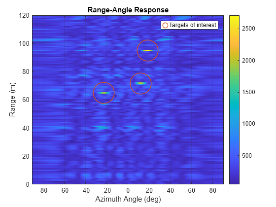
Combine range-angle responses computed from all received blocks using non-coherent integration, then plot the range-angle response.
rar_integ = sum(abs(rar), 3);

figure;
imagesc(theta, r, rar_integ);
ax = gca;
set(ax, 'YDir', 'normal') ;

colorbar;
xlabel('Azimuth Angle (deg)');
ylabel('Range (m)');
title('Range-Angle Response');
grid on;
ylim(regionOfInterest(1, :));
hold on;
plot(targetAzimuth, targetRange, 'o', 'LineWidth', 1, 'MarkerSize', 32, 'Color', '#D95319',...
    'MarkerFaceColor', 'none', 'DisplayName', 'Targets of interest');
legend
Using signals received over multiple transmitted blocks compute the range-Doppler map.
rangeDopplerResponse = phased.RangeDopplerResponse('RangeMethod', 'FFT', 'DopplerOutput', 'Speed',...
    'OperatingFrequency', carrierFrequency, 'SampleRate', sampleRate, 'SweepSlope', bandwidth/modulationPeriod,...
    'PRFSource', 'Property', 'PRF', 1/blockDuration, 'ReferenceRangeCentered', false);

[rdr, r, doppler] = rangeDopplerResponse(conj(y));
doppler = doppler * (-1);   % -1 to account for conj in the range-do response
Combine signals from all transmit-receive paths using non-coherent integration and plot the range-doppler response.
figure;
rdr_integ = squeeze(sum(abs(rdr), 2));

figure;
imagesc(doppler, r, rdr_integ);
ax = gca;
set(ax, 'YDir', 'normal') ;

colorbar;
xlabel('Speed (m/s)');
ylabel('Range (m)');
title('Range-Doppler Response');
grid on;
xlim([-50 50]);
ylim(regionOfInterest(1, :));
hold on;
plot(targetRadialVelocity, targetRange, 'o', 'LineWidth', 1, 'MarkerSize', 32, 'Color', '#D95319',...
    'MarkerFaceColor', 'none', 'DisplayName', 'Targets of interest');
legend
At Downlink Receiver
This example simulates transmission of Nb outer coded PMCW blocks with each block carrying Ntx BPSK symbols. The following diagram shows the signal processing steps at the downlink receiver.

Due to delay, the end of the i-th block arrives to the downlink user during the next (i+1)-st iteration. Hence, to process the received signal, the downlink receiver must first buffer two consecutive blocks, then estimate the starting position of the current block, and finally process blockLength samples starting from that position.
Stack signals from the current and the following received blocks to simulate a buffer and then use helperCommChannelDelay helper function to estimate the start of the current received block.
commRxBuffer = [commRxSignal(:, 1:Nb); commRxSignal(:, 2:(Nb+1))];
d = helperCommChannelDelay(commRxBuffer(1:Nchip, :), prbs);
Process blockLength samples starting from the estimated start position.
idx = sub2ind(size(commRxBuffer), d + (0:blockLength-1).', repmat(1:Nb, blockLength, 1));
commRxBuffer = commRxBuffer(idx);
Separate received signals from different transmitters by removing the outer codes.
commRxSignalDecoded = helperDecodeMIMOPMCW(commRxBuffer, H);
Process each received block one at a time.
rxDataBpsk = zeros([Nb-numSoundBlocks Ntx]);
ir = 0;

for i = 1:Nb
    if mod(i - 1, M) == 0  % Estimate channel matrix if unmodulated PRBS was transmitted
        channelMatrix = fft(commRxSignalDecoded(:, :, i))./prbsDFT;
    else
        % Perform channel equalization
        commRxSignalEqualized = (fft(commRxSignalDecoded(:, :, i)) .* conj(prbsDFT))./channelMatrix;
        y = ifft(commRxSignalEqualized);

        % Demodulate the signal to obtain the BPSK symbols.
        [~, idx] = max(abs(y), [], 'linear');

        ir = ir + 1;
        rxDataBpsk(ir, :) = y(idx)/Nchip;
    end
end
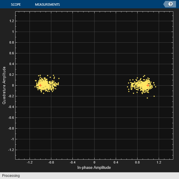
Plot the BPSK constelation for the received data.
refconst = pskmod([0 1], 2);
constellationDiagram = comm.ConstellationDiagram('NumInputPorts', 1, ...
    'ReferenceConstellation', refconst, 'ChannelNames', {'Received QAM Symbols'});

constellationDiagram(rxDataBpsk(:));
Compute the bit error rate.
rxDataBin = pskdemod(rxDataBpsk(:), 2);
[numErr,ratio] = biterr(txDataBin(:), rxDataBin(:))
numErr =
0
ratio =
0
Conclusion
This example simulates a radar-centric ISAC system. It begins by defining a scenario where a monostatic radar system simultaneously senses the surrounding environment and transmits a data payload to a downlink user. The setup includes a signaling scheme based on PMCW waveform and outer coding to implement a MIMO radar. Communication data is embedded into the transmitted radar waveform by multiplying the sequences transmitted by each transmit antenna with the corresponding data bits. The example shows transmission, propagation and reception of the generated waveform, followed by signal processing steps at both the radar and downlink user receivers. At the radar receiver, range-angle and range-Doppler responses are estimated, while at the downlink receiver, the transmitted data payload is recovered from the received signal.
References
de Oliveira, Lucas Giroto, Benjamin Nuss, Mohamad Basim Alabd, Axel Diewald, Mario Pauli, and Thomas Zwick. "Joint radar-communication systems: Modulation schemes and system design." IEEE Transactions on Microwave Theory and Techniques 70, no. 3 (2021): 1521-1551.
Sturm, Christian, and Werner Wiesbeck. "Waveform design and signal processing aspects for fusion of wireless communications and radar sensing." Proceedings of the IEEE 99, no. 7 (2011): 1236-1259.
Bourdoux, André, Ubaid Ahmad, Davide Guermandi, Steven Brebels, Andy Dewilde, and Wim Van Thillo. "PMCW waveform and MIMO technique for a 79 GHz CMOS automotive radar." In 2016 IEEE Radar Conference (RadarConf), pp. 1-5. IEEE, 2016.
Supporting Functions
function y = helperDecodeMIMOPMCW(xin, H)
% Combine received signals in the columns of xin based on the Hadamard
% matrix outer code in H
    [N, Nrx, Nb] = size(xin);
    Ntx = size(H, 1);
    L = N/Ntx;
    x = reshape(xin, L, Ntx, Nrx, Nb);
    y = zeros(L, Ntx, Nrx, Nb);

    for ntx = 1:Ntx
        h = repmat(H(ntx, :), L, 1, Nrx, Nb);
        y(:, ntx, :, :) = sum(x .* h, 2);
    end
end

function idx = helperCommChannelDelay(x, s)
% Estimate delay using cross-correlation
    Nb = size(x, 2);
    idx = zeros(1, Nb);
    for i = 1:Nb
        [r, lags] = xcorr(x(:, i), s);
        r = r(lags >= 0);
        [~, idx(i)] = max(abs(r));
    end
end

function vArray = helperVirtualArray(txArray, rxArray)
% Combine txArray and rxArray into a virtual array by convolving their
% apertures
    txElementPositions = getElementPosition(txArray);
    N = getNumElements(txArray);

    rxElementPositions = getElementPosition(rxArray);
    M = getNumElements(rxArray);

    vElemenetPositions = zeros(3, N*M);

    for m = 1:M
        vElemenetPositions(:, (m-1)*N+1:m*N) = rxElementPositions(:, m) + txElementPositions;
    end

    vArray = phased.ConformalArray('ElementPosition', vElemenetPositions);
end
