Interference from Satellite Constellation on Communications Link
This example shows how to analyze interference on a downlink from a constellation of satellites in a medium-Earth orbit (MEO) to a ground station located in the Pacific Ocean. The interfering constellation consists of 40 satellites in a low-Earth orbit (LEO). This example determines the times at which the downlink is closed, the carrier to noise plus interference ratio, and the link margin.
This example requires Satellite Communications Toolbox. If you have also have Antenna Toolbox™, you can use this example to learn how to import antennas from Antenna Toolbox into satellite scenario. If you also have Phased Array System Toolbox™, you can use this example to learn how to import antennas from Phased Array System Toolbox into satellite scenario and use beamforming to improve the carrier-to-noise-and-interference ratio (CNIR).
Create Satellite Scenario
Create a satellite scenario. Define the start time and stop time of the scenario. Set the sample time to 60 seconds.
startTime = datetime(2021,3,17,22,52,0);               % 17 March 2021 10:52 PM UTC
stopTime = startTime + minutes(10);                    % 17 March 2021 11:02 PM UTC
sampleTime = 60;                                       % In s
sc = satelliteScenario(startTime,stopTime,sampleTime);
Add Medium-Earth Orbit Satellite
Add a satellite in an MEO by specifying its Keplerian orbital elements. This satellite is the satellite from which data is downlinked.
semiMajorAxis = 12000000;                    % In m
eccentricity = 0;
inclination = 8;                             % In degrees
raan = 0;                                    % Right ascension of ascending node, in degrees
argOfPeriapsis = 0;                          % In degrees
trueAnomaly = 343.9391;                      % In degrees
meoSat = satellite(sc, semiMajorAxis, ...
    eccentricity, ...
    inclination, ...
    raan, ...
    argOfPeriapsis, ...
    trueAnomaly, ...
    Name = "MEO Satellite", ...
    OrbitPropagator = "two-body-keplerian");
Add Interfering Satellite Constellation
Add the interfering satellite constellation from a two-line-element (TLE) file. These satellites are placed in LEO.
interferingSat = satellite(sc,"leoSatelliteConstellation.tle");Add Transmitter to MEO Satellite
Add a transmitter to the MEO satellite. This transmitter is used for the downlink. Define the antenna specifications and set the operating carrier frequency to 3 GHz.
txMEOFreq = 3e9;                   % In Hz
txMEOSat = transmitter(meoSat, ...
    Frequency = txMEOFreq, ...     % In Hz
    Power = 11);                   % In dBW
gaussianAntenna(txMEOSat, ...
    DishDiameter = 1);             % In m
Add Transmitter to LEO Satellites
Add a transmitter to each satellite in the LEO constellation, and then define the antenna specifications. These transmitters are the ones that interfere with the downlink from the MEO satellite. Set the operating carrier frequency of the interfering satellites to 2.99 GHz. The example assigns each interfering satellite a random power in the range from 10 to 20 dBW.
interferenceFreq = 2.99e9;                              % In Hz
rng("default");
txInterferingSat = transmitter(interferingSat, ...
    Frequency = interferenceFreq, ...                   % In Hz
    Power = 10+10*rand(1,numel(interferingSat)));       % In dBW
gaussianAntenna(txInterferingSat, ...
    DishDiameter = 0.2);                                % In m
Add Ground Station
Add a ground station to the satellite scenario by specifying its latitude and longitude.
gs = groundStation(sc, ...
    0, ...                    % Latitude in degrees
    180, ...                  % Longitude in degrees
    Name = "Ground station");
Specify Ground Station Antenna Type
For this example, you can choose from one of the following antennas:
Gaussian Antenna
Parabolic Reflector from Antenna Toolbox
Uniform Rectangular Array from Phased Array System Toolbox
% Select the desired ground station antenna. groundStationAntennaType ="Gaussian Antenna";
Add Receiver to Ground Station
Add a receiver to the ground station. If you selected Gaussian Antenna or Parabolic Reflector, attach the receiver to a gimbal, which is in turn attached to the ground station. Configure the gimbal to track the MEO satellite, so that the antenna also tracks the MEO satellite. If you selected Uniform Rectangular Array, attach the receiver directly to the ground station. Specify the mounting location and mounting angles of the gimbal and receiver, and the antenna specifications appropriately.
switch groundStationAntennaType
    case {"Gaussian Antenna","Parabolic Reflector"}
        % When Gaussian Antenna or Parabolic Reflector is selected, attach
        % a gimbal to the ground station.
        gim = gimbal(gs, ...
            MountingLocation = [0;0;-5], ... % In m
            MountingAngles = [0;180;0]);     % In degrees

        % Set the gimbal to track the MEO satellite.
        pointAt(gim,meoSat);

        if groundStationAntennaType == "Gaussian Antenna"
            % When Gaussian Antenna is selected

            % Create the receiver object and add it to the gimbal
            rxGs = receiver(gim, ...
                MountingLocation = [0;0;1]); % In m

            % Provide the Gaussian Antenna specifications
            gaussianAntenna(rxGs, ...
                DishDiameter = 0.8);         % In m
        else
            % When Parabolic Reflector is selected

            % Size the antenna based on the frequency
            % Requires Antenna Toolbox(TM)
            ant = design(reflectorParabolic,txMEOFreq);

            % Create the receiver object and add it to the gimbal
            rxGs = receiver(gim, ...
                Antenna = ant, ...
                MountingLocation = [0;0;1]); % In m
        end
    case "Uniform Rectangular Array"
        % When Uniform Rectangular Array is selected

        % Determine the wavelength of the downlink signal
        c = physconst('LightSpeed');
        lambda = c/txMEOFreq;

        % Define array size
        nrow = 8;
        ncol = 8;

        % Define element spacing
        drow = lambda/2;
        dcol = lambda/2;

        % Create a back-baffled 6-by-6 antenna array
        % Requires Phased Array System Toolbox(TM)
        ant = phased.URA(Size = [nrow ncol], ...
            ElementSpacing = [drow dcol]);
        ant.Element.BackBaffled = true;

        % Create the receiver object and add it to the ground station
        rxGs = receiver(gs, ...
            Antenna = ant, ...
            MountingAngles = [0;90;0]); % In degrees
end
Create Access Analysis Between Interfering Satellite Constellation and Ground Station
Add an access analysis between each satellite in the interfering constellation and the ground station. This analysis enables the visualization of interference in the satellite scenario viewer that will be launched later. Any time a satellite in the constellation is visible to the ground station, there is some level of interference from that visible satellite.
ac = access(interferingSat,gs);
ac.LineColor = [1 1 0];              % Yellow
Set Tracking Targets for Satellites
Set the satellites to track the ground station. This ensures that the transmitter antennas on board each satellite track the ground station. Setting the interfering satellite transmitters to track the ground station results in the worst-case interference on the downlink.
pointAt([meoSat interferingSat],gs);
Calculate Weights of Uniform Rectangular Array
If you selected Uniform Rectangular Array as the ground station antenna, compute the weights that are required to point the main lobe towards the MEO satellite, and the nulls towards the interfering satellites, thereby canceling the interference. Assign the computed weights using pointAt.
if groundStationAntennaType == "Uniform Rectangular Array"
    % Find the LEO satellites that are in the line of sight of the ground
    % station. These satellites are the potential interferers.
    currentInterferingSat = interferingSat(accessStatus(ac,sc.StartTime) == true);

    % Calculate the direction of the MEO satellite with respect to the
    % array. This is the lookout direction.
    [azd,eld] = aer(rxGs,meoSat,sc.StartTime,CoordinateFrame='body');

    % Calculate the directions of the potentially interfering satellites
    % with respect to the array. These are the null directions.
    [azn,eln] = aer(rxGs,currentInterferingSat,sc.StartTime,CoordinateFrame='body');

    % Calculate the steering vectors for the lookout direction.
    % Requires Phased Array System Toolbox.
    wd = steervec(getElementPosition(ant)/lambda,[wrapTo180(azd);-eld]);

    % Calculate the steering vector for null directions.
    % Requires Phased Array System Toolbox.
    wn = steervec(getElementPosition(ant)/lambda,[wrapTo180(azn)';-eln']);

    % Compute the response of the desired steering at null directions.
    rn = (wn'*wn)\(wn'*wd);

    % Sidelobe canceler - remove the response at null directions.
    w = wd-wn*rn;

    % Assign the weights to the phased array.
    pointAt(rxGs,Weights=w);
end
Create Desired Downlink
Create a downlink from the transmitter on board the MEO satellite to the receiver on board the ground station. This link is the downlink which encounters interference from the LEO constellation.
downlink = link(txMEOSat,rxGs);
Create Interfering Links
Create a link between the transmitter on board each satellite in the LEO constellation and the receiver on board the ground station. These links are the interferer links with the desired downlink.
lnkInterference = link(txInterferingSat,rxGs);
Launch Satellite Scenario Viewer
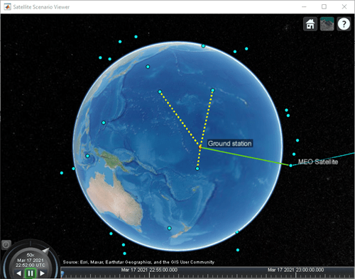
Launch the Satellite Scenario Viewer with ShowDetails set to false. When the ShowDetails property is set to false, only the satellites, the ground station, accesses, and links will be shown. The labels and orbits will be hidden. Mouse over the satellites and the ground stations to show their labels. Click on the MEO satellite so that its orbit projected up to the scenario StopTime and its label are visible without mousing over. Click on the ground station so that its label is visible without mousing over. The presence of the green line between the transmitter on board the MEO satellite and the receiver on board the ground station signifies that the downlink can be closed successfully assuming no interference from the satellite constellation exists. The presence of yellow lines between a given satellite in the constellation and the ground station signifies that they have access to one another, and as a result, interference from that satellite exists.
v = satelliteScenarioViewer(sc,ShowDetails=false);
Visualize Radiation Pattern of Antennas Involved in Downlink
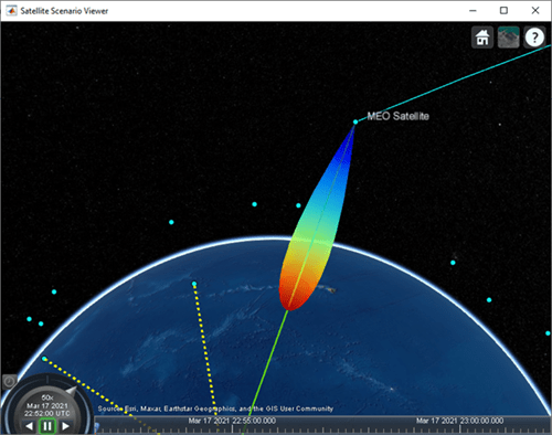
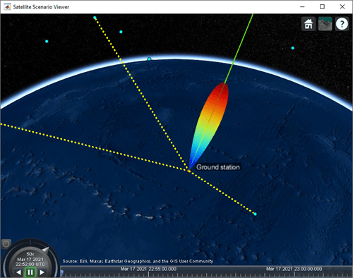
Visualize the radiation pattern of the transmitter antenna on board the MEO satellite and the receiver on board the ground station.
pattern(txMEOSat, ...
    Size = 1000000);        % In m
pattern(rxGs,txMEOFreq, ...
    Size = 1000000);        % In m
Radiation Pattern of MEO Satellite Antenna
Set Camera to View Ground Station Antenna Radiation Pattern
% Set camera position and orientation to view the ground station antenna
% radiation pattern.
campos(v,-8,172,2500000);
camheading(v,40);
campitch(v,-60);
Gaussian Antenna

Parabolic Reflector

Uniform Rectangular Array
Simulate Scenario and Visualize
With Gaussian Antenna or Parabolic Reflector
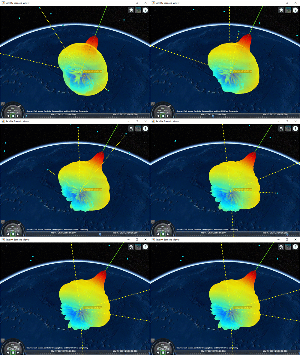
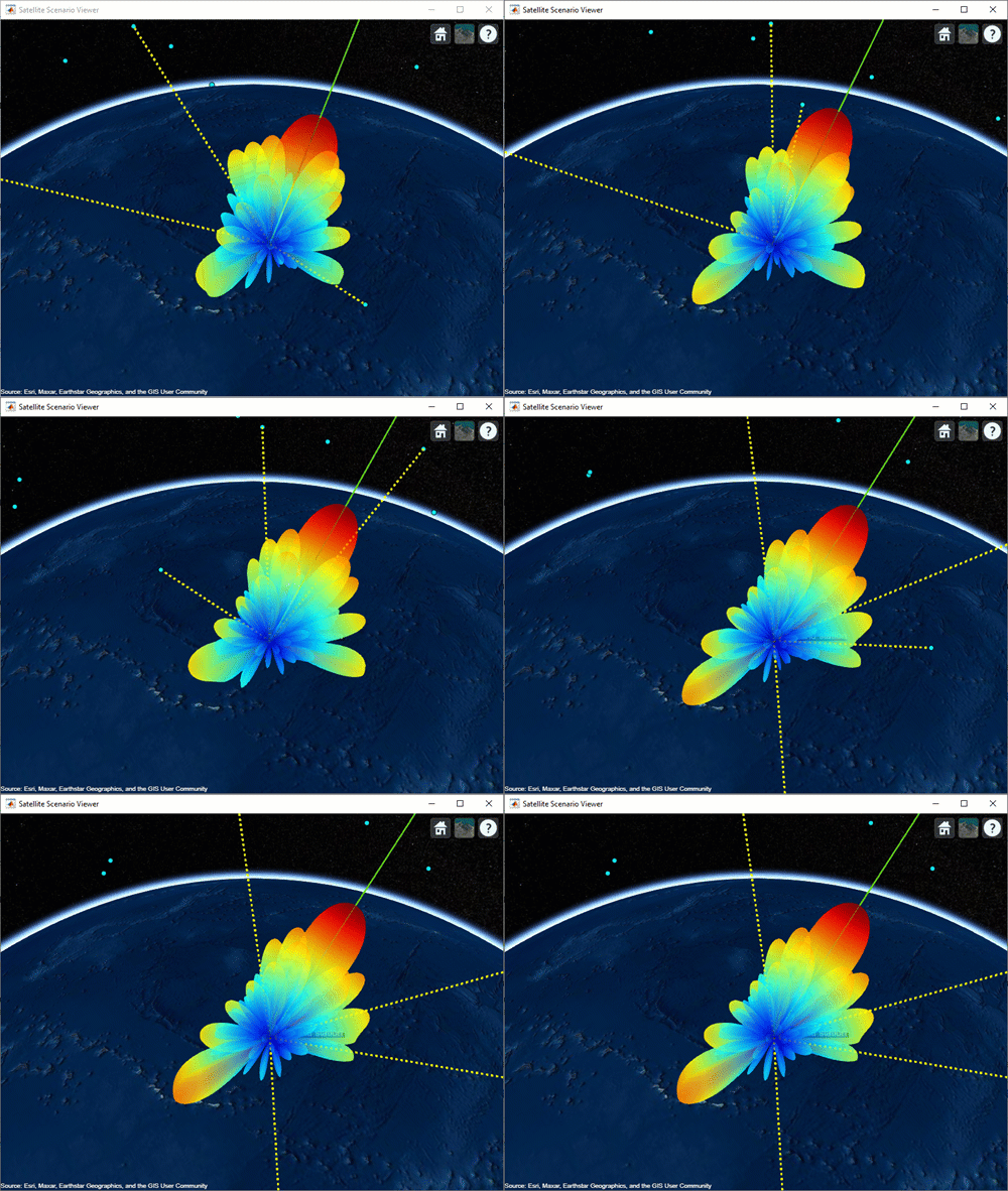
If you selected Gaussian Antenna or Parabolic Reflector (requires Antenna Toolbox), use play to visualize the scenario from StartTime to StopTime. This will automatically simulate the scenario before playing back the visualization. Note how the antenna pointing changes as the gimbal tracks the MEO satellite.
if groundStationAntennaType == "Gaussian Antenna" || groundStationAntennaType == "Parabolic Reflector"
    play(sc);
    campos(v,-8,172,2500000);
    camheading(v,40);
    campitch(v,-60);
end
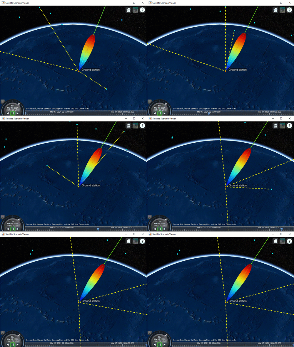
With Gaussian Antenna
With Parabolic Reflector
With Uniform Rectangular Array
If you selected Uniform Rectangular Array (requires Phased Array System Toolbox), you must manually step through the simulation so that you can recompute the weights at each time step based on the new position of the MEO satellite and the interfering LEO satellites. To manually step through the simulation, first set AutoSimulate to false. Following this, you can call advance to move the simulation by one time step. The first call to advance will compute the simulation states at StartTime. Subsequent calls will advance the time step by one SampleTime and compute the states accordingly.
if groundStationAntennaType == "Uniform Rectangular Array"
    % Set AutoSimulate to false.
    sc.AutoSimulate = false;

    % Manually step through the simulation.
    while advance(sc)
        % Determine the access status history for each LEO satellite
        % corresponding to the current SimulationTime.
        acStatusHistory = accessStatus(ac);
        acStatus = acStatusHistory(:,end);

        % Determine the LEO satellites that are visible to the ground
        % station. These are the satellites that will potentially
        % interfere with the ground station at the current simulation
        % time.
        currentInterferingSat = interferingSat(acStatus == true);

        % Determine the direction of the MEO satellite in the body frame of
        % the Uniform Rectangular Array. This is the lookout direction of
        % the array.
        [azdHistory,eldHistory] = aer(rxGs,meoSat,CoordinateFrame='body');
        azd = azdHistory(:,end);
        eld = eldHistory(:,end);

        % Determine the direction of these interfering satellites in
        % the body frame of the Uniform Rectangular Array. These are
        % the directions in which the array must point a null.
        [aznHistory,elnHistory] = aer(rxGs,currentInterferingSat,CoordinateFrame='body');
        azn = aznHistory(:,end);
        eln = elnHistory(:,end);

        % Calculate the steering vectors for lookout direction.
        % Requires Phased Array System Toolbox.
        wd = steervec(getElementPosition(ant)/lambda,[wrapTo180(azd);-eld]);

        % Calculate the steering vector for null directions.
        % Requires Phased Array System Toolbox.
        wn = steervec(getElementPosition(ant)/lambda,[wrapTo180(azn)';-eln']);

        % Compute the response of desired steering at null direction.
        rn = (wn'*wn)\(wn'*wd);

        % Sidelobe canceler - remove the response at null direction.
        w = wd-wn*rn;

        % Assign the weights to the phased array.
        pointAt(rxGs,Weights=w);
    end
end
Plot Downlink Closure Status Neglecting Interference
Determine the closure status of the desired downlink from the MEO satellite. The linkStatus function neglects interference from other transmitters. Any time the downlink is closed, the status is true. Otherwise, the status is false. The status is indicated by 1 and 0, respectively in the plot.
[downlinkStatus,t] = linkStatus(downlink);
plot(t,downlinkStatus,"-g",LineWidth=2);
xlabel("Time");
ylabel("Downlink Closure Status");
title("Link Status as a Function of Time");
grid on;

Calculate Downlink Closure Status with Interference
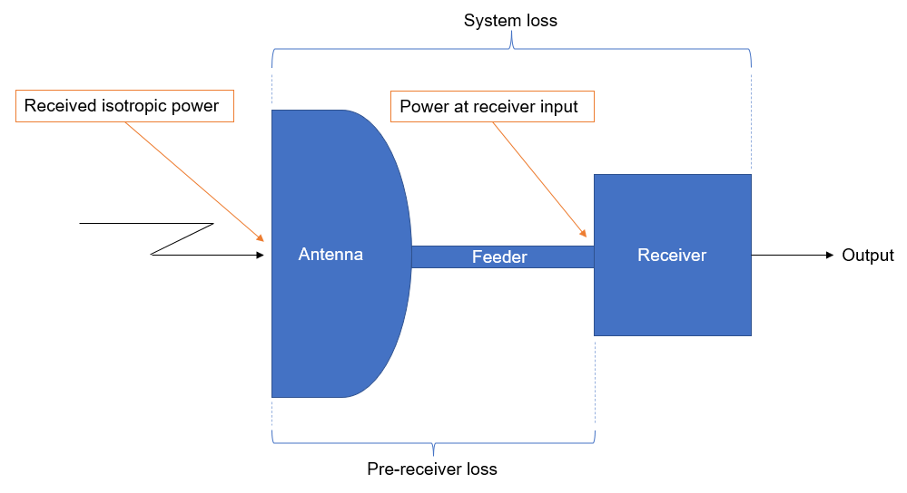
Calculate the downlink closure status with interference by first calculating the MEO downlink and interference signal power levels at the ground station receiver input using sigstrength. The locations of received power measurements and losses are illustrated in the ground station receiver diagram below.
% Calculate the power at receiver input corresponding to the downlink from
% the MEO satellite.
[~,downlinkPowerRxInput] = sigstrength(downlink); % In dBW

% Calculate the interference power at receiver input corresponding to each
% LEO satellite.
[~,interferencePowerRxInput] = sigstrength(lnkInterference); % In dBW
Calculate total interfering signal power at the receiver input. Get this quantity by summing the individual power levels from the interfering LEO satellites in Watts.
interferencePowerRxInputW = 10.^(interferencePowerRxInput/10); % W
interferencePowerRxInputSumW = sum(interferencePowerRxInputW); % W
Calculate the amount of total interfering signal power that contributes to interference in the signal bandwidth by following these steps.
1) Calculate the overlapping portion of the signal bandwidth with the bandwidth of the interferers. This example considers the transmission power of interfering satellites and the MEO satellite as constant across the whole bandwidth of respective MEO satellite and interfering satellites.
2) Calculate the amount of interference power that acts as interference to signal bandwidth.
This diagram shows the power spectral density (PSD) plot, which shows the actual interference power and modeled interference power when the transmission bandwidth and interfering bandwidth overlap. The actual interference power is the area occupied by the interference power density in the overlapped bandwidth region. This actual interference power is then spread across the entire transmission bandwidth and assumed to be noise-like.

This example assumes that the transmission (or signal) bandwidth of the MEO satellite is 30 MHz and that the bandwidth of the interfering signal is 20 MHz.
txBandwidth = 30e6;                                               % In Hz
interferenceBandWidth = 20e6;                                     % In Hz

% Get the overlap portion of the interfering bandwidth and the bandwidth of
% interest. The assumption is to the have same interference power across
% the whole bandwidth.
overlapFactor = getOverlapFactor(txMEOFreq,txBandwidth, ...
    interferenceFreq,interferenceBandWidth);

% Get the interference power that contributes as interference to the signal
% of interest from the total interference power
interferencePowerRxInputActual = interferencePowerRxInputSumW*overlapFactor; % In W
Interference is modeled by treating the contribution of interfering signal power in the overlapped bandwidth as noise. Accordingly, add this quantity to the thermal noise at the ground station receiver input. Note that the interference and noise power levels must be added in Watts.
% Calculate the thermal noise at the ground station receiver input.
T = HelperGetNoiseTemperature(txMEOFreq,rxGs); % In K
kb = physconst("Boltzmann");
thermalNoise = kb*T*txBandwidth;               % In W

% Calculate the noise plus interference power at the receiver input.
noisePlusInterferencePowerW = thermalNoise + interferencePowerRxInputActual; % In W
noisePlusInterferencePower = 10*log10(noisePlusInterferencePowerW);          % In dBW
Calculate the carrier to noise plus interference power spectral density ratio at the demodulator input as follows:
,
where:
is the carrier to noise plus interference power density ratio at the demodulator input (in dB).
is the received downlink power from the MEO satellite measured at the ground station receiver input (in dBW).
is the sum of receiver system thermal noise and the contribution of interfering signal power in the overlapped bandwidth measured at the receiver input (in dBW).
is the downlink transmission bandwidth from MEO satellite (in Hz).
is the loss that occurs between the receiver input and the demodulator input (in dB).
% Calculate loss that occurs between the receiver input and the demodulator
% input.
rxGsLoss = rxGs.SystemLoss - rxGs.PreReceiverLoss;

% Calculate C/(N0+I0) at the demodulator input.
CNoPlusInterference = downlinkPowerRxInput - ...
    noisePlusInterferencePower + 10*log10(txBandwidth) - rxGsLoss;
Calculate the energy per bit to noise plus interference power spectral density ratio at the demodulator input as follows:
,
where:
is the energy per bit to noise plus interference power spectral density ratio at the demodulator input (in dB).
is the bit rate of the downlink from the MEO satellite (in Mbps).
bitRate = txMEOSat.BitRate;
ebNoPlusInterference = CNoPlusInterference - 10*log10(bitRate) - 60;
Calculate the link margin as follows:
where:
is the link margin (in dB).
is the minimum received energy per bit to noise power spectral density ratio at the demodulator input that is required to close the link (in dB).
marginWithInterference = ebNoPlusInterference - rxGs.RequiredEbNo;
Calculate the downlink closure status with interference. The status is true whenever the link margin is greater than or equal to 0 dB.
downlinkStatusWithInterference = marginWithInterference >= 0;
Calculate Energy per Bit to Noise Power Spectral Density Ratio
Calculate the energy per bit to noise power spectral density ratio (Eb/N0) of the downlink and interfering links at the demodulator input for analysis later.
ebnoDownlink = ebno(downlink);            % In dB
ebnoInterference = ebno(lnkInterference); % In dB
Plot Downlink Closure Status with Interference
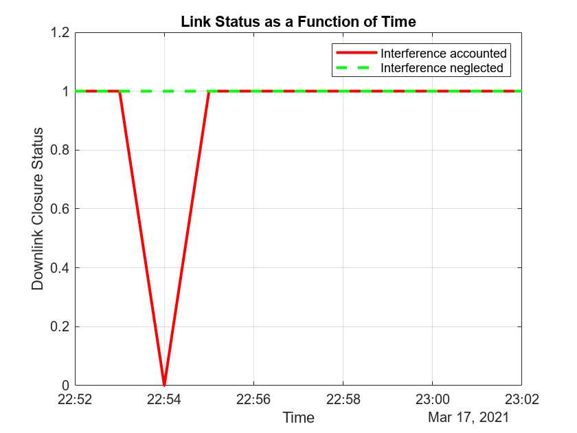
Plot the new downlink closure status that accounts for interference. Compare the new link status with the previous case when interference was neglected.
plot(t,downlinkStatusWithInterference,"-r",t,downlinkStatus,"--g",LineWidth=2);
legend("Interference accounted","Interference neglected");
xlabel("Time");
ylabel("Downlink Closure Status");
title("Link Status as a Function of Time");
ylim([0 1.2]);
grid on
When Gaussian Antenna or Parabolic Reflector are Chosen
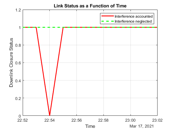
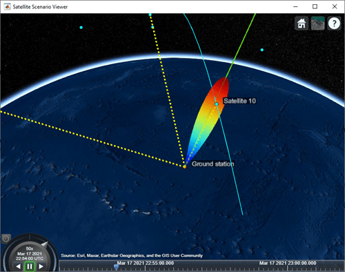
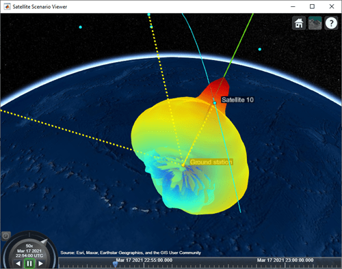
The plot shows that at 10:54 PM, the downlink cannot be closed because of excessive interference. This occurs because Satellite 10 of the LEO constellation flies overhead, and its transmission is picked up by its main lobe. This can also be visually confirmed by setting the current time of the viewer to 10:54 PM and clicking on the satellite near the main lobe of the antenna. Note that you require Antenna Toolbox to select Parabolic Reflector.
if groundStationAntennaType == "Gaussian Antenna" || groundStationAntennaType == "Parabolic Reflector"
    v.CurrentTime = datetime(2021,3,17,22,54,0);
end
Gaussian Antenna
Parabolic Reflector
When Uniform Rectangular Array with Interference Cancelation Is Chosen

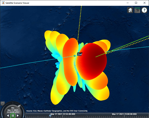
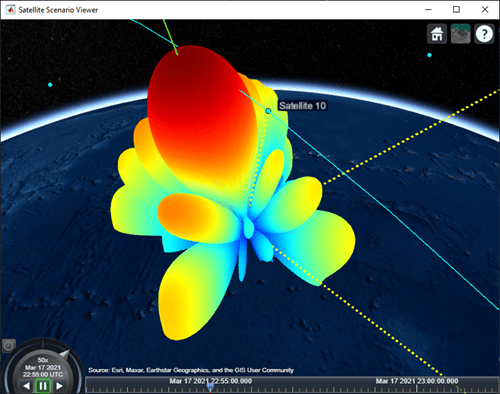
If you selected Uniform Rectangular Array (requires Phased Array System Toolbox), the plot shows that the downlink can be closed for the duration of the scenario because the array is pointing nulls towards the direction of the interfering LEO satellites. This can also be visually confirmed by setting the current time of the viewer to 10:54 PM and 10:55 PM. To be able to manually set the viewer CurrentTime, you must change AutoSimulate to true. Note that this will clear the simulation data. Also, you will be required to re-compute the weights for these times and assign them to the array using pointAt. The satellite that is overflying the ground station is Satellite 10. Click on it to see its name and orbit. Drag the mouse while holding down on the left mouse button or scroll button to bring the camera to the desired position and orientation. Rotate the scroll wheel to control camera zoom. Additionally, make the radiation pattern opaque to clearly visualize the position of Satellite 10 with respect to the lobes. You can see that at both times, Satellite 10 is in between lobes. This is because the array is pointing a null towards the satellite, thereby canceling interference from it.
if groundStationAntennaType == "Uniform Rectangular Array"
    % Set AutoSimulate to true.
    sc.AutoSimulate = true;

    % Set viewer CurrentTime to 10:54 PM.
    time = datetime(2021,3,17,22,54,0);
    v.CurrentTime = time;

    % Calculate the weights and assign them to the array.
    currentInterferingSat = interferingSat(accessStatus(ac,time) == true);
    [azd,eld] = aer(rxGs,meoSat,time,CoordinateFrame='body');
    [azn,eln] = aer(rxGs,currentInterferingSat,time,CoordinateFrame='body');

    % Requires Phased Array System Toolbox.
    wd = steervec(getElementPosition(ant)/lambda,[wrapTo180(azd);-eld]);
    wn = steervec(getElementPosition(ant)/lambda,[wrapTo180(azn)';-eln']);

    rn = (wn'*wn)\(wn'*wd);
    w = wd-wn*rn;
    pointAt(rxGs,Weights=w);

    % Make the radiation pattern opaque.
    pattern(rxGs,txMEOFreq, ...
        Size = 1000000, ...
        Transparency = 1);
end
At 10:54 PM UTC
You can run the above code with time set to 10:55 PM and observe the nulls pointing towards the new positions of the interfering satellites.
At 10:55 PM UTC
Calculate and Plot Carrier to Noise Ratio and Carrier to Noise Plus Interference Ratio
Calculate the carrier to noise ratio (CNR) at the demodulator input as follows:
,
,
where:
is the carrier to noise ratio at the demodulator input (in dB).
is the carrier to noise power spectral density ratio at the demodulator input (in dB).
% Calculate the carrier to noise power spectral density ratio.
CNoDownlink = ebnoDownlink + 10*log10(bitRate) + 60;

% Calculate the carrier to noise ratio.
cByN = CNoDownlink - 10*log10(txBandwidth);
Calculate the carrier to noise plus interference ratio (CNIR) at the demodulator input as follows:
cByNPlusI = CNoPlusInterference - 10*log10(txBandwidth);
Plot CNR and CNIR
plot(t,cByNPlusI,"-r",t,cByN,"--g",LineWidth=2);
legend("CNIR", "CNR",Location="south");
xlabel("Time");
ylabel("CNR or CNIR (dB)");
title("CNR and CNIR vs. Time for " + groundStationAntennaType);
grid on
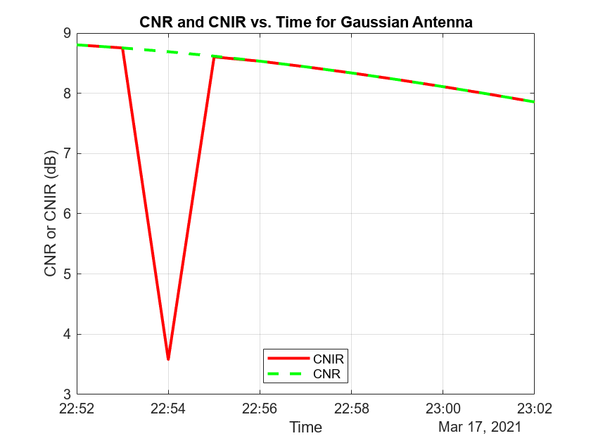
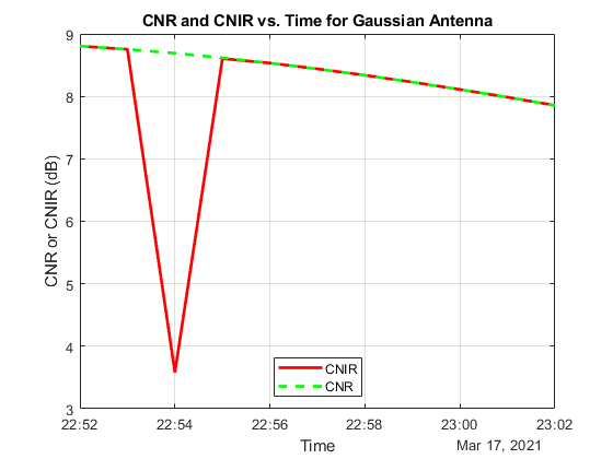
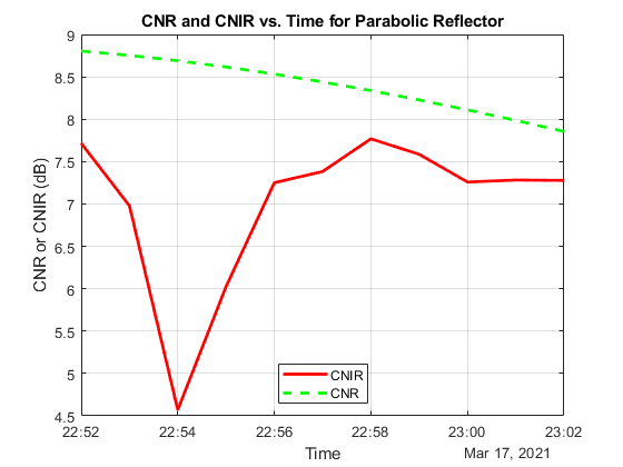
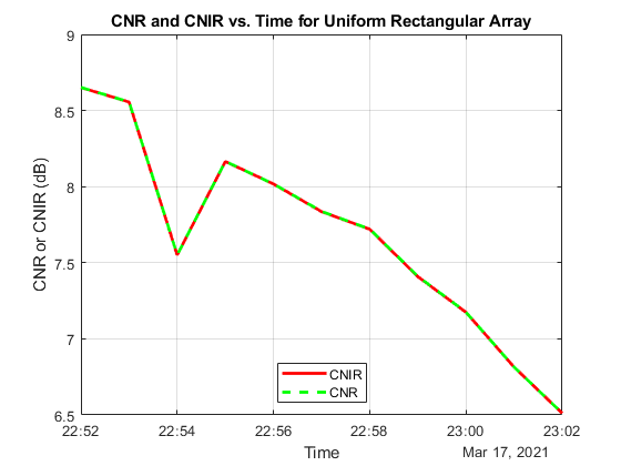
When Uniform Rectangular Array (requires Phased Array System Toolbox) with MEO satellite tracking and interference cancelation is chosen, both CNR and CNIR overlap because there is no interference from the LEO satellites. This is because the array is pointing nulls towards the LEO satellites. This can be confirmed by noting that the maximum power at ground station receiver input from the interfering satellites is about -167.3 dBW, which is very low. For all other antennas used in this example, the maximum power at ground station receiver input is much higher (-125.9 dBW for Gaussian Antenna, and -127.3 dBW for Parabolic Reflector).
maxInterferencePowerRxInput = max(interferencePowerRxInput,[],'all');
disp("The maximum power at ground station receiver input from the interfering LEO satellites over the entire scenario duration is " + maxInterferencePowerRxInput + " dBW.");
The maximum power at ground station receiver input from the interfering LEO satellites over the entire scenario duration is -125.9277 dBW.
Compare Link Margins with and without Interference
Calculate the link margin without interference as follows:
marginWithoutInterference = ebnoDownlink - rxGs.RequiredEbNo;
Plot the link margins with and without interference.
plot(t,marginWithInterference,"-r",t,marginWithoutInterference,"--g",LineWidth=2);
legend("With interference","Without interference",Location="south");
xlabel("Time");
ylabel("Margin (dB)");
title("Link Margin vs. Time for " + groundStationAntennaType);
grid on
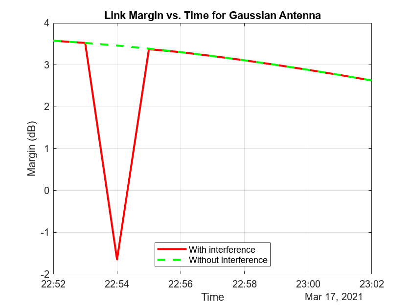

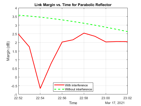
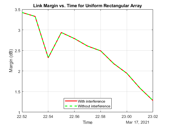
Any time the link margin is greater than or equal to 0 dB, the downlink is closed. With Gaussian Antenna, Parabolic Reflector (requires Antenna Toolbox), and Uniform Rectangular Array (requires Phased Array System Toolbox) without interference cancelation, there exist times when the link margin dips below 0 dB because of interference. At these times, the downlink is broken.
Further Exploration
This example demonstrates how to analyze interference on a satellite communication link. The link closure times are a function of these parameters:
The orbit of the satellites
The position of the ground station
The specifications of the transmitters and the receiver
The specifications of the transmitter and receiver antennas
Weights if using a Uniform Rectangular Array
The signal and interference bandwidth
Modify these parameters to observe their influence on the level of interference on the link. You can also choose the different antennas from Antenna toolbox and Phased Array System Toolbox for transmitters and receivers and observe the link performance. When using phased arrays and if you are only interested in making the main lobe track a single target and not deal with pointing nulls, you can use pointAt to automatically track other satellites, ground stations, and geographic locations without having to manually simulate by setting AutoSimulate to false. The limitation of calling play when using dynamically steered phased arrays is that you cannot visualize the variation of their radiation pattern over the course of the simulation.
Helper Functions
The example uses the helper function HelperGetNoiseTemperature to obtain the noise temperature of the receiver antenna.
The example also uses this local function to compute the amount of overlap between the transmission bandwidth and the interfering bandwidth.
function overlapFactor = getOverlapFactor(txFreq,txBW,interferenceFreq,interferenceBW)
% getOverlapFactor provides the amount of interference bandwidth overlapped
% with transmission bandwidth

    txFreq_Limits = [txFreq-(txBW/2) txFreq+(txBW/2)];
    interferenceFreq_Limits = [interferenceFreq-(interferenceBW/2) ...
        interferenceFreq+(interferenceBW/2)];
    if (interferenceFreq_Limits(2) < txFreq_Limits(1)) || ...
            (interferenceFreq_Limits(1) > txFreq_Limits(2))
        % If no overlap exists between transmission bandwidth and
        % interfering bandwidth, then overlap factor is 0
        overlapFactor = 0;
    elseif (interferenceFreq_Limits(2) <= txFreq_Limits(2)) && ...
            (interferenceFreq_Limits(1) >= txFreq_Limits(1))
        % If interfering bandwidth lies completely within transmission
        % bandwidth, then overlap factor is 1
        overlapFactor = 1;
    elseif (interferenceFreq_Limits(2) > txFreq_Limits(2)) && ...
            (interferenceFreq_Limits(1) < txFreq_Limits(1))
        % If transmission bandwidth lies completely within interfering
        % bandwidth, then overlap factor is the ratio of transmission
        % bandwidth with that of interference bandwidth
        overlapFactor = txBW/interferenceBW;
    elseif (interferenceFreq_Limits(2) <= txFreq_Limits(2)) && ...
            (interferenceFreq_Limits(1) <= txFreq_Limits(1))
        % If the start edge of transmission bandwidth lies within
        % interfering bandwidth, then overlap factor is the ratio of
        % difference from last edge of interfering bandwidth and first edge
        % of signal bandwidth, with that of interference bandwidth
        overlapFactor = (interferenceFreq_Limits(2)-txFreq_Limits(1))/interferenceBW;
    else
        % If the last edge of transmission bandwidth lies within
        % interfering bandwidth, then overlap factor is the ratio of difference
        % from last edge of signal bandwidth and first edge of interfering
        % bandwidth, with that of interference bandwidth
        overlapFactor = (-interferenceFreq_Limits(1)+txFreq_Limits(2))/interferenceBW;
    end

end