Iridium Satellite Spot Beam Coverage on the US
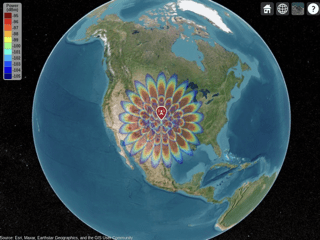
This example shows how to generate and visualize Iridium satellite spot beams on the US map. The Iridium satellite antenna array is created using Phased Array System Toolbox. The satellite position is generated and viewed using Satellite Communications Toolbox. The spot beam coverage map is displayed as the antenna array is steered.
Introduction
The Iridium satellite system is a low-Earth-orbit (LEO) satellite constellation system that provides high-quality voice and data communications. This system consists of 66 satellites distributed along six polar orbital planes. Each satellite’s main mission array (MMA) is a 120-element L-band uniform rectangular array (URA). The MMA can generate 48 fixed spot beams towards earth using analog beamforming technology.
Create an Iridium Satellite Main Mission Array
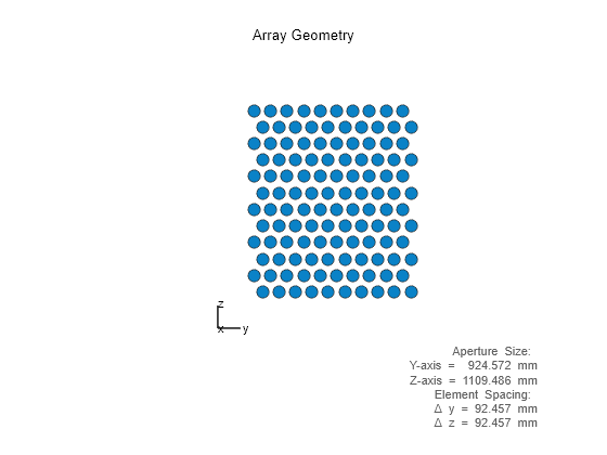
An Iridium satellite adopts a 12-by-10 element URA as its MMA. Configure the MMA using phased.URA.
% Iridium satellite frequency
freqLow = 1616e6;                                       % Hz
freqHigh = 1626.5e6;                                    % Hz
freq = (freqLow + freqHigh)/2;                          % Hz

% Determine the wavelength
lambda = physconst('LightSpeed')/freq;

% Define array size in row and column
nrow = 12;
ncol = 10;

% Define row and column element spacing
drow = lambda/2;
dcol = lambda/2;

% Configure Iridium 120-element MMA
iridiumArray = phased.URA(...
    'Size',[nrow ncol],...
    'ElementSpacing',[drow dcol],...
    'Lattice','Triangular');
iridiumArray.Element.BackBaffled = true;

% View Iridium MMA
figure
viewArray(iridiumArray)
View the 3D directivity pattern of Iridium MMA.
% Plot 3D directivity pattern of Iridium MMA
figure
pattern(iridiumArray,freq)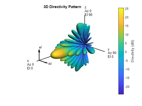
Create Satellite Scenario
Create a satellite scenario using satelliteScenario (Satellite Communications Toolbox). Specify a start time and duration of 60s for the scenario.
% Define start and end time
startTime = datetime(2021,3,17,22,52,0);               % 17 March 2021 10:52 PM UTC
stopTime = startTime + minutes(1);                     % 17 March 2021 10:53 PM UTC
sampleTime = 60;                                       % s

% Configure satellite scenario
sc = satelliteScenario(startTime,stopTime,sampleTime);
Set Keplerian elements of an Iridium satellite such that the satellite passes above the US.
% Define the semimajor axis of the orbit of the satellite
semiMajorAxis = (6371 + 780)*1e3;                       % m

% Define the shape of the orbit of the satellite
eccentricity = 0;

% Define the inclination angle
inclination = 86.4;                                     % degrees

% Define the argument of periapsis
argOfPeriapsis = 0;                                     % degrees

% Define the right ascension of ascending node
raan = 55;                                              % degrees

% Define the true anomaly
trueAnomaly = 38;                                       % degrees
Configure the Keplerian elements of the Iridium satellite using the satellite (Satellite Communications Toolbox) function.
% Configure Iridium satellite
iridiumSat = satellite(sc, semiMajorAxis, ...
    eccentricity, ...
    inclination, ...
    raan, ...
    argOfPeriapsis, ...
    trueAnomaly, ...
    Name = "Iridium Satellite", ...
    OrbitPropagator = "two-body-keplerian");
View satellite scenario by using satelliteScenarioViewer (Satellite Communications Toolbox).
% Satellite scenario
v = satelliteScenarioViewer(sc,ShowDetails=false); 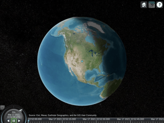
Configure Iridium Satellite 48 Spot Beam
The Iridium satellite has 48 spot beams. These beams are arranged in 4 tiers. The following figure shows the spot beam indices and the 4-tier structure with different tiers drawn in different colors.
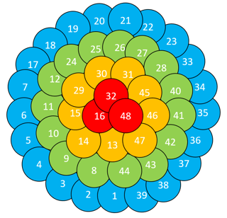
% Number of spot beams
numSpotBeam = 48;

% Define 48 spot beam indices in 4 tiers
tier1 = [16,32,48];                                     % inner-most beams
tier2 = [13:15,29:31,45:47];                            % inner-middle beams
tier3 = [8:12,24:28,40:44];                             % outer-middle beams
tier4 = [1:7,17:23,33:39];                              % outer-most beams

% Define transmission parameters
maxRange = 5e6;                                         % m
transmitterPower = 11;                                  % watts
thetaoffset = [11,19,33,45];                            % degrees

% Define signal strength range
sigstrengthlow = -105;                                  % dBm
sigstrengthhigh = -95;                                  % dBm
sigstrengths = sigstrengthlow:sigstrengthhigh;
sigcolors = [sigstrengthlow,sigstrengthhigh];
Display Iridium Satellite 48 Spot Beam Coverage on the US
The 48 spot beams are formed using transmit beamforming at the Iridium satellite. Configure steering vector of the Iridium array using phased.SteeringVector.
% Configure steering vector for spot beam beamforming
steeringvector = phased.SteeringVector("SensorArray",iridiumArray);
Obtain Iridium satellite position using states (Satellite Communications Toolbox) function of the Satellite (Satellite Communications Toolbox) object.
% Obtain Iridium satellite position
iridiumpos = states(iridiumSat,startTime,"CoordinateFrame","geographic");
Create the satellite as a txsite (Communications Toolbox) in siteviewer (Communications Toolbox), which supports terrestrial RF propagation analysis and visualization.
% Configure site viewer to view spot beams
viewer = siteviewer('Terrain','none');

% Loop beam index to plot 48 spot beams
for beamIdx = 1:numSpotBeam
    % Configure phi/theta angles for each spot beam
    if any(ismember(beamIdx,tier1))
        k = find(beamIdx == tier1);
        phi = 360/numel(tier1)*(k-1);                   % degrees
        theta = thetaoffset(1);                         % degrees
    elseif any(ismember(beamIdx,tier2))
        k = find(beamIdx == tier2);
        phi = 360/numel(tier2)*(k-1);                   % degrees
        theta = thetaoffset(2);                         % degrees
    elseif any(ismember(beamIdx,tier3))
        k = find(beamIdx == tier3);
        phi = 360/numel(tier3)*(k-1);                   % degrees
        theta = thetaoffset(3);                         % degrees
    else
        k = find(beamIdx == tier4);
        phi = 360/numel(tier4)*(k-1);                   % degrees
        theta = thetaoffset(4);                         % degrees
    end

    % Convert steering angle from phi/theta form to azimuth/elevation form
    azel = phitheta2azel([phi;theta]);

    % Set transmit beamforming weights for a spot beam
    sv = steeringvector(freq,azel);
    iridiumArray.Taper = sv';

    % Configure the transmit site for a spot beam
    spotbeam = txsite("Name","Iridium-Next Satellite Tx",...
        "Latitude",iridiumpos(1), ...
        "Longitude",iridiumpos(2), ...
        "AntennaHeight",iridiumpos(3),...
        "Antenna",iridiumArray,...
        "AntennaAngle",[0;-90],...
        "TransmitterFrequency",freq,...
        "TransmitterPower",transmitterPower);

    % Plot 3D beam pattern in animation
    pattern(spotbeam)

    % Display coverage map
    coverage(spotbeam,"freespace",...
        'MaxRange',maxRange,...
        'SignalStrengths',sigstrengths,...
        'ColorLimits',sigcolors)
end
Summary
This example shows how to create an antenna array using Phased Array System Toolbox. This example also shows how to generate a satellite scenario using Satellite Communications Toolbox. Through this example, you learned how to display different beams generated by an antenna array on a map.
Reference
[1] Attachment EngineeringStatement SAT-MOD-20131227-00148. https://fcc.report/IBFS/SAT-MOD-20131227-00148/1031348. Accessed 9 June. 2023.
[2] Attachment Exhibit A SAT-MOD-20131227-00148. https://fcc.report/IBFS/SAT-MOD-20131227-00148/1031240. Accessed 9 June. 2023.
[3] Manual for ICAO Aeronautical Mobile Satellite (Route) Service, Part 2-Iridium, Draft v4.0. https://www.icao.int/safety/acp/Inactive%20working%20groups%20library/ACP-WG-M-Iridium-8/IRD-SWG08-IP05%20-%20AMS(R)S%20Manual%20Part%20II%20v4.0.pdf. Accessed 9 June. 2023.
[4] L. Yu, J. Wan, K. Zhang, F. Teng, L. Lei and Y. Liu, "Spaceborne Multibeam Phased Array Antennas for Satellite Communications," in IEEE Aerospace and Electronic Systems Magazine, vol. 38, no. 3, pp. 28-47, 1 March 2023, doi: 10.1109/MAES.2022.3231580.
