Swerling Target Models
The example illustrates the use of Swerling target models to describe the fluctuations in radar cross-section. The scenario consists of a rotating monostatic radar and a target having a radar cross-section described by a Swerling 2 model. In this example, the radar and target are stationary.
Swerling 1 versus Swerling 2 Models
In Swerling 1 and Swerling 2 target models, the total RCS arises from many independent small scatterers of approximately equal individual RCS. The total RCS may vary with every pulse in a scan (Swerling 2) or may be constant over a complete scan consisting of multiple pulses (Swerling 1). In either case, the statistics obey a chi-square probability density function with two degrees of freedom.
Dwell Time and Radar Scan
For simplicity, start with a rotating radar having a rotation time of 5 seconds corresponding to a rotation or scan rate of 72 degrees/sec.
Trot = 5.0;
scanrate = 360/Trot;
The radar has a main half-power beam width (HPBW) of 3.0 degrees. During the time that a target is illuminated by the main beam, radar pulses strike the target and reflect back to the radar. The time period during which the target is illuminated is called the dwell time. This time is also called a scan. The radar will process 3 scans of the target.
HPBW = 3.0;
Tdwell = HPBW/scanrate;
Nscan = 3;
The number of pulses that arrive on target during the dwell time depends upon the pulse repetition frequency (PRF). PRF is the inverse of the pulse repetition interval (PRI). Assume 5000 pulses are transmitted per second.
prf = 5000.0;
pri = 1/prf;
The number of pulses in one dwell time is
Np = floor(Tdwell*prf);
Set up a Swerling 2 model
You create a Swerling 2 target by using the RadarTarget System object™. To effect a Swerling 2 model, set the Model property of the phased.RadarTarget System object to either 'Swerling1' or 'Swerling2'. Both are equivalent. Then, at every call to the object, set the updatercs argument to true. This argument means that the radar cross-section is updated at every pulse.
Set the target model to 'Swerling1'.
tgtmodel = 'Swerling2';
Set up radar model System object components
Set up the radiating antenna. Assume the operating frequency of the antenna is 1 GHz.
fc = 1e9;
antenna = phased.IsotropicAntennaElement('BackBaffled',true);
radiator = phased.Radiator('OperatingFrequency',fc,'Sensor',antenna);
Specify the location of the stationary antenna.
radarplatform = phased.Platform('InitialPosition',[0;0;0]);
Specify the location of a stationary target.
targetplatform = phased.Platform('InitialPosition',[2000; 0; 0]);
The transmitted signal is a linear FM waveform. Transmit one pulse per call to the object.
waveform = phased.LinearFMWaveform('PulseWidth',50e-6,...
    'OutputFormat','Pulses','NumPulses',1);
Set up the transmitting amplifier.
transmitter = phased.Transmitter('PeakPower',1000.0,'Gain',40);
Set up the propagation environment to be free space.
channel = phased.FreeSpace('OperatingFrequency',fc,...
    'TwoWayPropagation',true);
Specify the radar target to have a mean RCS of 1 m2 and be of the Swerling model type 1 or 2. You can use Swerling 1 or 2 interchangeably.
target = phased.RadarTarget('MeanRCS',1,'OperatingFrequency',fc,...
    'Model',tgtmodel);
Set up the radar collector.
collector = phased.Collector('OperatingFrequency',1e9,...
    'Sensor',antenna);
Define a matched filter to process the incoming signal.
wav = waveform();
mfilter = phased.MatchedFilter(...
    'Coefficients',getMatchedFilter(waveform));
Processing loop for 3 scans of a Swerling 2 target
Generate waveform with unit amplitude
Amplify the transmit waveform
Radiate the waveform in the desired direction to the target
Propagate the waveform to and from the radar target
Reflect waveform from radar target.
Collect radiation to create received signal
Match filter received signal
Provide memory for radar return amplitudes.
z = zeros(Nscan,Np);
tp = zeros(Nscan,Np);
Enter the loop. Set updatercs to true only for the first pulse of the scan.
for m = 1:Nscan
    t0 = (m-1)*Trot;
    t = t0;
    updatercs = true;
    for k = 1:Np
        t = t + pri;
        txwav = transmitter(wav);
Find the radar and target positions
        [xradar,vradar] = radarplatform(t);
        [xtgt,vtgt] = targetplatform(t);
Radiate waveform to target
        [~,ang] = rangeangle(xtgt,xradar);
        radwav = radiator(txwav,ang);
Propagate waveform to and from the target
        propwav = channel(radwav,radarplatform.InitialPosition,...
            targetplatform.InitialPosition,[0;0;0],[0;0;0]);
Reflect waveform from target. Set the updatercs flag.
reflwav = target(propwav,updatercs);
Collect the received waveform
collwav = collector(reflwav,ang);
Apply matched filter to incoming signal
        y = mfilter(collwav);
        z(m,k) = max(abs(y));
        tp(m,k) = t;
    end
end
Plot the pulse amplitudes
Plot the amplitudes of the pulses for the scan as a function of time.
plot(tp(:),z(:),'.')
xlabel('Time (sec)')
ylabel('Pulse Amplitude')

Notice that the pulse amplitudes vary within a scan.
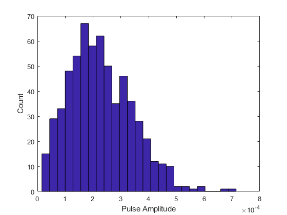
Histogram the received pulse amplitudes
figure;
hist(z(:),25)
xlabel('Pulse Amplitude')
ylabel('Count')
