Model, Simulate, and Generate Code for Ladder Logic-Based Elevator Controller
Rapidly prototype the ladder logic-based controller for a single car elevator by using Simulink® PLC Coder™ to model and simulate the ladder logic. After verifying that the controller works for your requirements, generate code for the controller.
Model Description
The model consists of a Elevator Control System block, Elevator Block, and a Human Machine Interface (HMI) block. Open the model:
open_system('plcdemo_ladder_elevator');
Opening the model loads the timer configuration, model data types, and initializes the model by using information from the plcdemo_ladder_elevator_init.m file.
type plcdemo_ladder_elevator_init% sample time Ts = 0.1; % load PLC builtin types plcloadtypes; % define timer initial values T37_InitialValue = FB_TON.InitialValue; T37_InitialValue.PRE = int32(300*100); T38_InitialValue = FB_TOF.InitialValue; T38_InitialValue.PRE = int32(100*100); T39_InitialValue = FB_TON.InitialValue; T39_InitialValue.PRE = int32(12*100); T40_InitialValue = FB_TON.InitialValue; T40_InitialValue.PRE = int32(10*100); T41_InitialValue = FB_TOF.InitialValue; T41_InitialValue.PRE = int32(1*100); % define dashboard parameters InteriorFloor1Request = false; InteriorFloor2Request = false; InteriorFloor3Request = false; InteriorFloor4Request = false; ExteriorFloor1Request = false; ExteriorFloor2Request = false; ExteriorFloor3Request = false; ExteriorFloor4Request = false; Photocell = false;
Elevator Control System Block
The Elevator Control System block is a PLC Controller block. It contains a Ladder Program block that contains the ladder logic. To view the ladder logic for the controller, open:
The
Elevator Control SystemblockThe
Elevator PLC Ladder Diagram SystemblockThe
Elevator ControllerblockThe
TaskblockThe
Programblock
This image shows a section of the ladder diagram logic inside the Program block.

HMI Block
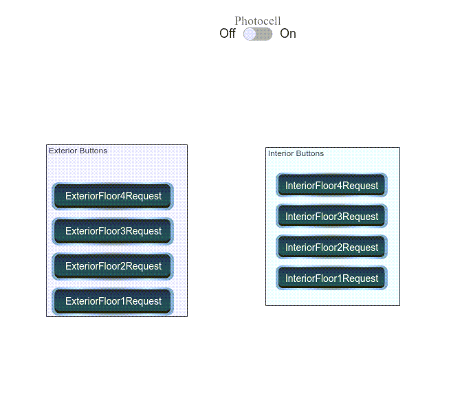
The HMI Block enables you to interact with the model simulation. Open the HMI block by double-clicking the block. This image shows the components of the HMI block.

The HMI block contains:
Exterior Buttons: Represents the exterior floor request buttons.
Interior Buttons: Represents the interior floor request buttons.
Photocell: Represents the door sensor.
Elevator Block
The Elevator block is a MATLAB Function Block that contains a mathematical model representing the elevator system. The calculations from the Elevator block are used as inputs to the graphics function to simulate the elevator movement.
Simulate Model and Generate Code
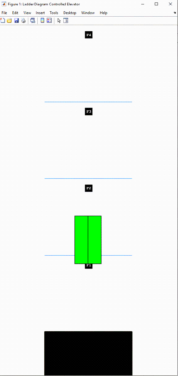
Simulate the model and observe the elevator animation. In this image, the second floor external request button was pressed.

After verifying that the controller functions for your requirements, generate code for the Elevator Controller block
plcgeneratecode('plcdemo_ladder_elevator/Elevator Control System/Elevator PLC Ladder Diagram System/Elevator Controller')
Alternatively, generate code by selecting the Elevator Controller block, and then selecting APPS > PLC Coder. On the PLC Code tab, click Generate PLC Code.