Read and Process Raw ADC Data in Real-time from TI mmWave Radar Board Using DCA1000EVM Capture Card
R2026bThis example shows how to use Radar Toolbox Support Package for Texas Instruments® mmWave Radar Sensors to acquire raw ADC radar data (IQ data) from Texas Instruments (TI) radars for real-time processing.
Additionally, this example includes instructions on how to evaluate and visualize the range response and range-doppler response using the ADC data collected from the TI radar.
This example supports boards operating in Time Division Multiplexing (TDM) and Doppler Division Multiplexing (DDM) modes. For DDM-enabled boards, the phase-coding sequence repeats every P chirps, where P is the phase-code period. For example, on the AWR2944EVM DDM processing chain, the phase-code period is 6 chirps (4 active transmitters and 2 empty subbands). To remove the periodic DDM phase modulation, the example selects every sixth chirp and forms a consistent slow-time signal. This allows the Doppler FFT to estimate target velocity correctly.
Required Products
MATLAB®
Radar Toolbox Support Package for Texas Instruments mmWave Radar Sensors
For information on installing the support package, see Install Support and Perform Hardware Setup for TI mmWave Hardware.
Required Hardware
One of the supported TI mmWave Radar Evaluation Modules (EVM) that supports reading raw ADC data (IQ data) by connecting to DCA1000EVM (see Supported Boards)
USB Cable Type A to Micro B
Power Adaptor: Either 5V, 3 A power adapter (for AWR1642BOOST, IWR1642BOOST, AWR1843BOOST) or 12V, 2.5A power adapter (for AWR2944EVM). In both cases, it is recommended that you connect two power adapters of the same kind to the two independent power input connectors in these boards.
DCA1000EVM capture card
Samtec cable
Ethernet cable
Hardware Setup
You must set up the TI mmWave radar sensor and DCA1000EVM before you can use it to read ADC data to MATLAB. Set up the sensor by completing the hardware setup procedure (as explained in the Hardware Setup screens). To launch hardware setup, execute the below command and follow the steps shown in the screens.
mmWaveRadarSetup
For information on launching the Hardware Setup screens, see Install Support and Perform Hardware Setup for TI mmWave Hardware.
Connect to mmWave Radar and DCA1000 Capture card
After the hardware setup process is completed successfully, you can connect to the TI Radar board and DCA1000EVM by specifying the board name. This example uses the IWR6843ISK EVM. If you are using a different EVM, change the board name accordingly.
dca = dca1000("IWR6843ISK");If you have connected only one TI Radar board to the host computer, MATLAB detects the serial port details automatically. If you have connected more than one board or if MATLAB does not automatically populate the serial port details, specify the ConfigPort argument. For example:
dca = dca1000("IWR6843ISK",ConfigPort = "COM3")
Refer to Identifying Serial Ports for TI mmWave Radar Connection to identify the Config port corresponding to your board.
Note: If you are using a TI AWR2944EVM board, a successful connection also requires consistency of the processing chain between the firmware image, configuration file, and processing chain. This is because AWR2944EVM board supports both TDM (Time Division Multiplexing) and DDM (Doppler Division Multiplexing) processing chains, and the processing mode depends on which processing chain is flashed to the board by using the hardware setup with mmWaveRadarSetup. After the dca object creation, you can also use updateProcessingChain function to launch the corresponding hardware setup pages to update the processing chain.
DDM firmware enables simultaneous transmission from all TX antennas using Doppler-division phase coding, while TDM firmware enables TX antennas sequentially in a round-robin pattern. All other supported boards use TDM processing chain.
dca = dca1000("AWR2944EVM")
Configuring the TI Radar
To configure the TI mmWave radar board, you must send a sequence of commands to the board using the serial port. The sequence includes commands specifying the chirp profile, sampling rate, and so on. Use the ConfigFile property of the dca1000 object to send the sequence of commands to the board. For more information, see Configure Radar Using a Configuration (.cfg) File for Reading Raw ADC (IQ) Data.
In this example, we will be using a default configuration that ships with support package.
For the AWR2944EVM, the default configuration file also depends on the flashed firmware. The DDM configuration (AWR294X_profile_DDM_DCA.cfg) configures all 4 TX with simultaneous transmission and DDM phase coding. The TDM configuration (AWR294X_profile_TDM_DCA.cfg) configures round-robin TX activation. You can specify a custom configuration file using:
dca = dca1000("AWR2944EVM", ConfigFile="<path to config.cfg>")
Compute and Visualize Range Response and Range-Doppler Response Using the Live Radar ADC Data (IQ data) Obtained from TI Radar Board
Calling the dca1000 object retrieves a single radar data cube from the TI radar board. This function call returns a radar data cube with dimensions: (Number of ADC samples)-by-(Number of Rx channels)-by-(Number of Chirps).
Number of ADC Samples, Number of Rx channels, and Number of Chirps are the values of the properties SamplesPerChirp, NumReceivers and NumChirps, respectively, of the dca1000 object. These values are set based on the Configuration (.cfg) file you are using to configure the TI mmWave radar.
Note: The first call to dca1000 object does the configuration, which might take some time. The subsequent calls to dca1000 object should be faster and returns ADC data as soon as the data is available.
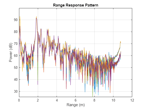
The below script reads radar data cubes and use phased.RangeResponse to assess and visualize the range response of the ADC data in real-time. The phased.RangeResponse System object™ is configured to perform range filtering on fast-time (range) data, using an FFT-based algorithm. plotResponse function of the phased.RangeResponse is used to plot the range response of the input data.
Note: For the AWR2944EVM, range processing is the same for both TDM and DDM modes. The Range FFT operates on the fast-time (intra-chirp) ADC samples, and each chirp uses the same FMCW waveform parameters, including bandwidth, sample rate, and sweep slope, regardless of the MIMO multiplexing scheme. As a result, range computation is identical in both modes. Because range resolution () depends only on chirp bandwidth, not on TX antenna multiplexing, you can use the same phased.RangeResponse configuration for both TDM and DDM boards.
clear dca
% Create connection to TI Radar board and DCA1000EVM Capture card
dca = dca1000("IWR6843ISK");
% Define a variable to set the sampling rate in Hz for the
% phased.RangeResponse object. The dca1000 object provides the
% sampling rate in kHz; convert this rate to Hz.
fs = dca.ADCSampleRate*1e3;
% Define a variable to set the FMCW sweep slope in Hz/s for the
% phased.RangeResponse object. The dca1000 object provides the
% sweep slope in MHz/us; convert this sweep slope to Hz/s.
sweepSlope = dca.SweepSlope * 1e12;
% Define a variable to set the number of range samples
nr = dca.SamplesPerChirp;
% Create phased.RangeResponse System object that performs range filtering
% on fast-time (range) data, using an FFT-based algorithm
rangeresp = phased.RangeResponse(RangeMethod = 'FFT',...
                                 RangeFFTLengthSource = 'Property',...
                                 RangeFFTLength = nr, ...
                                 SampleRate = fs, ...
                                 SweepSlope = sweepSlope, ...
                                 ReferenceRangeCentered = true);
% The first call of the dca1000 object may take longer due to the
% configuration of the radar and the DCA1000EVM. To exclude the configuration
% time from the loop's duration, make the first call to the dca1000 object
% before entering the loop.
iqData = dca();
% Specify the duration in seconds for which the loop should run
stopTime = 100;
% Start the stopwatch timer
ts = tic;
% Execute the loop until the stopTime specified is reached
while (toc(ts)<stopTime)
% Capture the ADC data (IQ data) from TI Radar board and DCA1000EVM
iqData = dca();
% Get the data from first receiver antenna
iqData = squeeze(iqData(:,1,:));
% Plot the range response corresponding to the input signal, iqData.
plotResponse(rangeresp,iqData);
% Update figures
drawnow limitrate;
end
% Stop streaming the data and release the non tunable properties
dca.release;
Compute and Visualize Range-Doppler Response
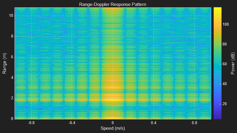
The script in this section reads radar data cubes in real-time and uses phased.RangeDopplerScope to compute and display the range-doppler response map.
Slow-time Subsampling for Range-Doppler Processing
Unlike range processing, which uses all chirps in the same way, Doppler processing requires selecting a subset of chirps that correspond to a specific transmit channel. The slow-time subsampling factor depends on the MIMO mode used by the board.
TDM Boards (for example, IWR6843ISK with 2 TX Antennas)
In TDM mode, transmit antennas operate sequentially in a round-robin pattern. For an IWR6843ISK with two transmit antennas, the chirp sequence is: TX0, TX1, TX0, TX1, ...
Selecting every second chirp (1:2:end) isolates the chirps transmitted by TX0. For TDM processing, the slow-time subsampling factor equals NumTransmitters. As a result, the effective pulse repetition interval (PRI) is:
Effective PRI = NumTransmitters × ChirpCycleTime
DDM Boards (for example, AWR2944EVM with 4 TX Antennas)
In DDM mode, all four transmit antennas transmit simultaneously on every chirp. Each antenna uses a unique phase code, where P is the phase-code period. The phase-code sequence repeats every six chirps, consisting of four active TX subbands and two empty subbands.
The processing uses the slow-time subsampling approach described in the Slow-Time Subsampling for Range-Doppler Processing section. In the AWR2944EVM DDM configuration used by this example, the DDM phase-coding sequence repeats every six chirps. Therefore, the algorithm selects every sixth chirp to remove the periodic DDM phase modulation and form a consistent slow-time signal before performing Range-Doppler processing.
For TX antenna on chirp , the DDM phase shift is:
where is the sub-band index for TX . Because of the fact that (the phase-coded period is 6), the chirps {1, 7, 13, 19, ...} all carry an identical composite DDM phase. Extracting these gives slow-time samples (numLoops) free of DDM modulation.
DDM phase coded period = num of active transmitters + 2 empty subband.
Selecting every sixth chirp (1:6:end) captures chirps for which all transmit antennas have returned to their initial phase state. This removes the effect of the DDM phase modulation and enables Doppler processing using a consistent phase reference. The effective PRI is:
Effective PRI = (NumTransmitters + 2) × ChirpCycleTime
Note: When the while loop in the below script is running, a MATLAB figure window opens up. You can move an object in front of the mmWave radar and see if the figure updates accordingly.
Note: The below script works for all TDM-based boards. If you are using an AWR2944EVM board with DDM processing chain, uncomment the line that starts with numChirpTypes = numTx + 2.
clear dca
% Create connection to TI Radar board and DCA1000EVM Capture card
dca = dca1000("IWR6843ISK");
% Initialize variables
% Define a variable to set the sampling rate in Hz for the
% phased.RangeDopplerScope object. Because the dca1000 object provides the
% sampling rate in kHz, convert this rate to Hz.
fs = dca.ADCSampleRate*1e3;
% Define a variable to set the center frequency in Hz for the
% phased.RangeDopplerScope object. Because the dca1000 object provides the
% center frequency in GHz, convert this rate to Hz.
fc = dca.CenterFrequency*1e9;
% Define a variable to set the FMCW sweep slope in Hz/s for the
% phased.RangeDopplerScope object. The dca1000 object provides the
% sweep slope in MHz/us; convert this sweep slope to Hz/s.
sweepslope = dca.SweepSlope*1e12;
% Samples per chirp or RangeFFTLength
nr = dca.SamplesPerChirp;
% Number of active receivers
nrx = dca.NumReceivers;
% Number of chirps per frame
nchirp = dca.NumChirps;
% Number of transmitters
numTx = dca.NumTransmitters;
% Chirp slow-time subsampling factor for TDM: equals the number of TX antennas.
% For IWR6843ISK (2 TX TDM): chirp sequence is TX0,TX1,TX0,TX1,...
% so every 2nd chirp (1:2:end) isolates TX0.
% For boards with more TX in TDM mode, the slow-time subsampling factor = numTx.
numChirpTypes = numTx;   % TDM: one chirp type per TX antenna


% For AWR2944EVM (DDM mode), uncomment the following line:
% numChirpTypes = numTx + 2;   % DDM: phase code period (4 active TX + 2 empty subbands)

% In DDM, all TX transmit on every chirp with phase codes that repeat
% every 6 chirps. Extracting every 6th chirp cancels the DDM phase
% modulation, leaving only target-induced Doppler phase shift.
%
% Effective PRI = numChirpTypes * chirpCycleTime
% This is the time between same-phase-state chirps:
%   TDM:  numTx * Tc (time for TX round-robin to return to same antenna)
%   DDM:  6 * Tc (time for DDM phase code to complete one full period)
tpulse = numChirpTypes*dca.ChirpCycleTime*1e-6;
% Pulse repetition frequency
prf = 1/tpulse;
% Number of slow-time samples after slow-time subsampling
numLoops = nchirp / numChirpTypes;
% Create range doppler scope to compute and display the response map.
rdscope = phased.RangeDopplerScope(IQDataInput=true,...
    SweepSlope = sweepslope,SampleRate = fs,...
    DopplerOutput="Speed",OperatingFrequency=fc,...
    PRFSource="Property",PRF=prf,...
    RangeMethod="FFT",RangeFFTLength=nr, ...
    ReferenceRangeCentered = true);
% The first call of the dca1000 class object may take longer due to the
% configuration of the radar and the DCA1000EVM. To exclude the configuration
% time from the loop's duration, make the first call to the dca1000 object
% before entering the loop.
iqData = dca();
fprintf('Data cube size: [%d x %d x %d] (samples x receivers x chirps)\n', size(iqData));
fprintf('Chirp slow-time subsampling: every %d chirps -> %d slow-time samples\n', numChirpTypes, numLoops);
fprintf('Effective PRF: %.1f Hz\n', prf);
% Specify the duration in seconds for which the loop should run
stopTime  = 150;
ts = tic();
% Execute the loop until the stopTime specified is reached
while (toc(ts)<stopTime)
    % Capture the ADC data (IQ data) from TI Radar board and DCA1000EVM
    iqData = dca();
    % Extract every numChirpTypes-th chirp from Rx1 to isolate one
    % TX phase state:
    %   TDM: selects chirps from one TX antenna (others are silent)
    %   DDM: selects chirps where all TX phase codes realign (period=6),
    %        so the DDM modulation cancels and only Doppler phase remains
    iqData = squeeze(iqData(:,1,1:numChirpTypes:end));
    % Plot the range doppler response corresponding to the input signal.
    rdscope(iqData);
end
% Stop streaming the data and release the non tunable properties
dca.release;
