Radar Architecture: System Components and Requirements Allocation (Part 1)
This example is the first part of a two-part series that shows you how to use Simulink® to design and model a radar system given a set of requirements, and test the expected performance. It starts by introducing a set of performance requirements that must be satisfied by the final design. A radar system architecture is then developed using System Composer™. The example then shows how to connect the radar requirements to the architecture and a corresponding design. Finally, it shows how to create a functioning model of a radar system by providing concrete implementations to the components of the architecture.
The second example in the series discusses testing the model and verification of the requirements. It shows how to use Simulink Test™ to set up test suites and run Monte Carlo simulations to verify the linked requirements. Radar Architecture: Test Automation and Requirements Traceability (Part 2) also explores a scenario when the stated requirements have been revised. It shows how to trace the changes in the requirements to the corresponding components of the design and make modifications to the implementation and tests. You will leverage underlying radar models from related example Simulating Test Signals for a Radar Receiver in Simulink.
Performance Requirements
Radar system design typically begins with a set of requirements. The real-world radar systems must satisfy dozens or hundreds of requirements. In this example we consider an X-band radar system that must satisfy the following two performance requirements:
R1: The radar must detect a Swerling 1 Case target with a radar cross section (RCS) of 1 m at the range of 6000 m with a probability of detection of 0.9 and the probability of false alarm of 1e-6.
R2: When returns are detected from two Swerling 1 Case targets separated in range by 70 m, with the same azimuth and elevation, the radar must resolve the two targets and generate two unique target reports 80 percent of the time.
Virtual Test Bed
As the first step, the example shows how to set up a virtual test bed for a radar system that will be used to implement and test the design. This test bed is useful for tracing the performance requirements to the individual components of the system, making iterative design changes, and testing and verifying the performance of the system. The example starts by creating a general top-level architecture model using System Composer. It then shows in more detail an architecture of a radar sensor component and the part of the test bed that simulates the environment and the radar targets.
Top-Level Architecture
The architecture model specifies only the conceptual components of the system, their interfaces, and links between them. The components of the architecture model are not required to have a concrete implementation. As will be shown further in this example, System Composer allows for defining specific Simulink behavior for some of the components while leaving other components specified only at the architecture level. A modular design like this is convenient and flexible since the behavior of the individual components can be modified or completely changed without the need to make any changes to other parts of the system.
In addition to the Radar Sensor component that models the actual radar sensor, the test bed also includes:
Power Substation— Supplies power to the radar sensor.Control Center— Passes control commands to the radar sensor throughCommunications Linkand receives the radar data back.Targets and Environment— Models the radar waveform propagation through the environment and the interaction of the waveform with the targets.Radar Sensoris connected toTarget and Environmentthrough a set of ports markedTx,Rx, andTargetsPos.TxandRxlinks are used to pass the radar waveform to and fromTargets and Environment.TargetsPosis used to pass the information about the target positions toRadar Sensorin order to simulate the transmitted and received waveform in the directions of the targets.
Open the top-level architecture.
open_system('slexRadarArchitectureExample')
Radar Sensor
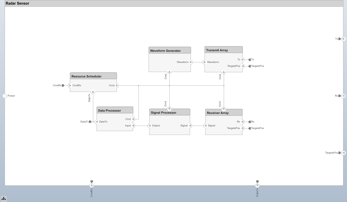
Each component in an architecture model can be further decomposed into subcomponents. As a next step, define architecture for a radar sensor. When Radar Sensor is decomposed, Power, Tx, Rx, CmdRx, and DataTx ports defined at the top level become available as the external ports. Open the Radar Sensor component.
open_system("slexRadarArchitectureExample/Radar Sensor");

Define the following components to create an architecture model of a radar sensor:
Resource Scheduler— Responsible for allocating the system resources within a dwell. It receives control commands fromControl Centerthrough the external CmdRx port. To indicate the flow of the control signals in the radar sensor architecture,Resource Scheduleris also linked to every component insideRadar Sensor.Waveform Generator— Produces samples of the radar waveform.Transmit Array— Passes the transmitted waveform toTarget and Environmentthrough the externalTxport.Receiver Array— Receives back the reflected waveform fromTarget and Environmentthrough the externalRxport.Signal Processor— Performs beamforming, matched filtering, and pulse integration and passes the detections toData Processor.Data Processor— Creates radar reports or radar tracks and passes them back toControl Center.
This architecture model of a radar sensor is very general. It does not make any assumptions about the type of a transmitted waveform, the shape or size of the antenna array, or the implementation of the signal and the data processing chains. The same architecture can be used to implement a large variety of different radar sensors. Further, this example implements only a subset of the listed components leaving out Resource Scheduler and Data Processor.
Targets and Environment
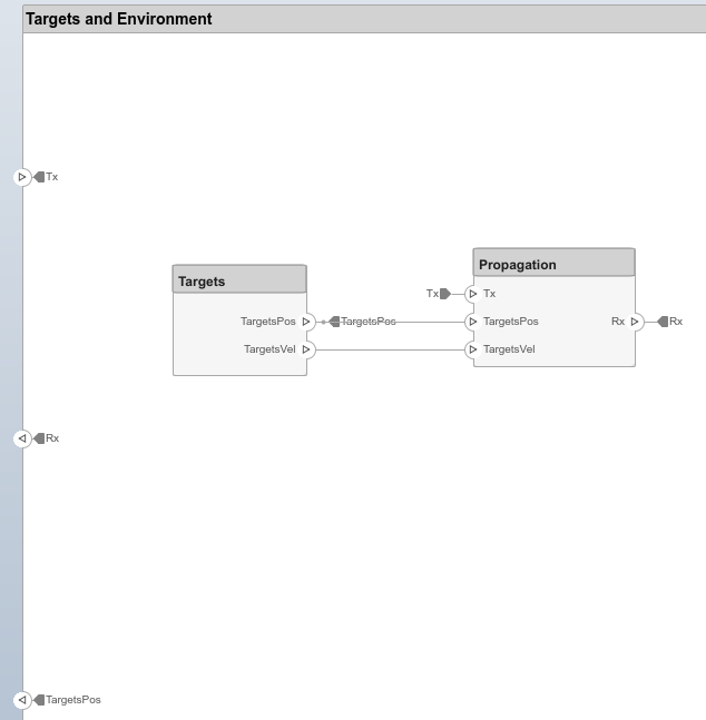
Targets and Environment can be decomposed into two subcomponents:
Targets— Outputs positions and velocities of targets.Propagation— Models the propagation of the plane wave emitted byTransmit Arraythrough the environment, reflection from the radar targets, and propagation back toReceiver Array.
Open Targets and Environment component.
open_system("slexRadarArchitectureExample/Targets and Environment")

Requirements Traceability
Requirements Toolbox™ is a tool that provides a way to link the requirements to the components of the architecture responsible for implementing the corresponding functionality. When either the requirements or the model change, Requirements Toolbox provides a convenient way to trace the changes to the corresponding tests and verify that the performance and the requirements are always in agreement.
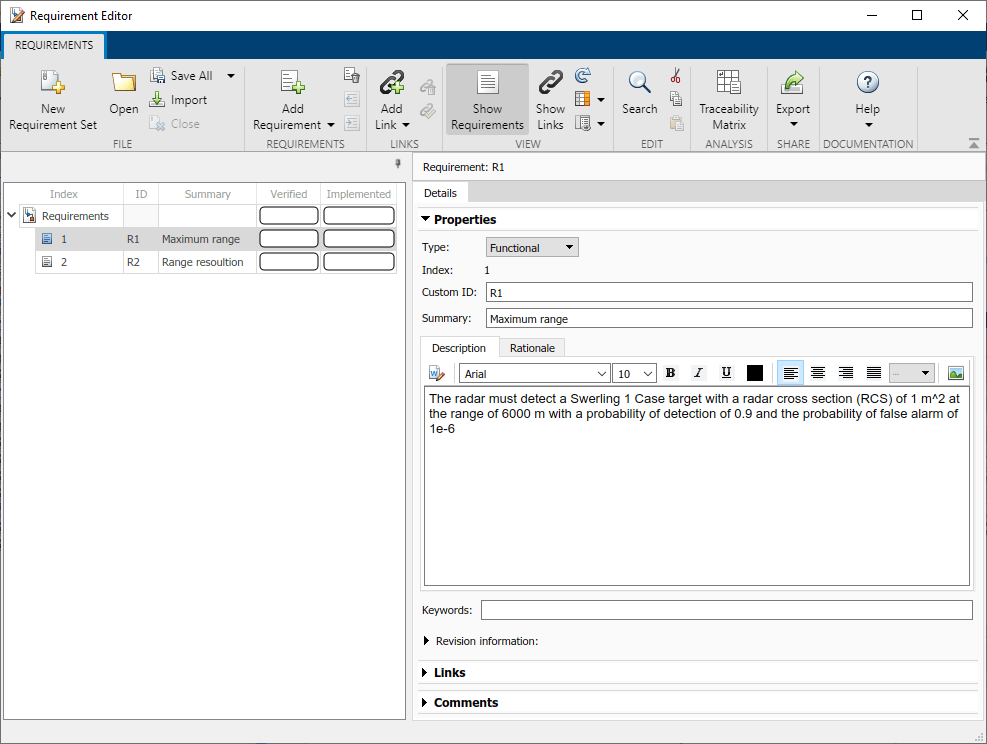
Launch the Requirements Manager app through the Apps tab. Then access Requirements Editor by navigating to the Requirements tab and selecting Requirements Editor. To create a new set of requirements for the model, click on New Requirement Set. For this example, create a requirements set and add R1 and R2 to it. Open these requirements in Requirements Editor.
open('slreqRadarArchitectureExampleRequirements.slreqx')

Requirements Editor lists the maximum range and the range resolution requirements. In the left panel it also shows the Verified and Implemented status for each requirement. At this moment, both requirements are not implemented and not verified. In order to change the Implemented status of a requirement, link it to a component of the architecture that implements the corresponding function. Link both requirements to Waveform Generator and Signal Processor. Requirements Perspective also shows the status of R1 and R2 in the bottom pane. After linking the requirements to the components, Requirements Perspective shows that the status of R1 and R2 has changed to Implemented. When a requirement is selected in Requirements Perspective, the components to which it is linked are highlighted with a purple frame. The linked components are also shown in the Links sections of the Details tab on the right.

Another convenient way to visualize the links between the requirements and the components of the architecture is the Traceability Matrix that can be generated by clicking on Traceability Matrix in the Requirements tab. It clearly shows which components are responsible for the implementation of each requirement.

Component Implementation
To simulate a radar system, provide a concrete behavior to the components of the architecture model. System Composer allows for you to specify the behavior of some components in Simulink, while leaving the behavior of other components undefined. This provides a lot of flexibility to the design and simulation since you can build a functioning and testable model with some of the components modeled in detail while other components defined only at the abstract level. This example only specifies the concrete behavior for the components of the radar sensor needed to implement generation, transmission, reception, and processing of the radar signal. It also provide a concrete implementation to Targets and Environment.
To specify the dimensions of signals within the model, the example assumes that the target positions are specified by a three-row matrix, tgtpos, the targets velocities are specified by a three-row matrix, tgtvel, and the targets RCS are specified by a vector, tgtrcs.
System Parameters
To provide the Simulink behavior to the components of the radar sensor, first identify a set of radar design parameters that could satisfy the stated requirements. A set of parameters for a radar system that would satisfy R1 and R2 can be quickly found by performing a radar range equation analysis in the Radar Designer app. The app computes a variety of radar performance metrics and visualizes the detection performance of the radar system as a function of range. We use the Metrics and Requirements table to set the objective values of the maximum range and the range resolution requirements to the desired values specified in R1 and R2. Then we adjust the system parameters until the stoplight chart indicates that the performance of the system satisfies the objective requirement. The resulting set of the radar design parameters is:
Main: Frequency — 10 GHz
Main: Peak Power — 6 kW
Main: Pulse Width — 0.4
Main: Pulse Bandwidth — 2.5 MHz
Main: PRF — 20 kHz
Hardware: Noise Figure — 0 dB
Antenna and Scanning: Transmit Antenna Gain — 26 dBi
Detection and Tracking: Number of Pulses — 10

Open this design in Radar Designer app.
radarDesigner('RadarDesigner_RectangularWaveform.mat')
Waveform Generator
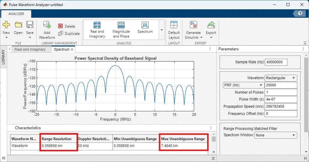
The analysis performed in the Radar Designer app assumes the time-bandwidth product to be equal to 1. This means that the transmitted waveform is an unmodulated rectangular pulse. Use the Pulse Waveform Analyzer app to confirm that the derived waveform parameters result in the desired performance and satisfy R1 and R2.
Start the Pulse Waveform Analyzer app with the waveform parameters defined in this example.
pulseWaveformAnalyzer('PulseWaveformAnalyzer_RectangularWaveform.mat')
The app shows that the range resolution and the unambiguous range agree well with the requirements.

To implement this behavior in the radar model, the Waveform Generator component needs to contain only a single Simulink block generating a rectangular waveform. Connect the output of the Rectangular Waveform block to the external Waveform port linked to the Transmit Array component. Since this example does not consider the command signals, link Cmd input to a terminator.

Set the Output signal format property of the block to Pulses. This means that every pulse repetition interval (PRI) of 1/prf seconds, the block produces a column vector of fs/prf complex waveform samples.
Transmit Array
The Transmit Array component comprises the following Simulink blocks:
Transmitter— Transmits the waveform generated byWaveform Generatorwith the specified peak power and transmit gain.Range Angle Calculator— Computes the directions towards the targets assuming the radar is placed on static platform located at the origin. The target directions are used asAnginput toNarrowband Tx Array.Narrowband Tx Array— Models an antenna array for transmitting narrowband signals. It outputs copies of the transmitted waveform radiated in the directions of the targets.

The radar range equation analysis identified that the transmit gain should be 26 dB. Set the Gain property of the Transmitter block to 20 dB and use an antenna array to get an additional gain of 6 dB. A phased array antenna with the desired properties can be designed using the Sensor Array Analyzer app. For this example, use a 4-element uniform linear array that has array gain of approximately 6 dB.
Open the array model in the Sensor Array Analyzer app.
sensorArrayAnalyzer('SensorArrayAnalyzer_ULA.mat')

System Composer requires explicit specification of the dimensions, sample time, and complexity of the input signals. Set the dimensions of the Waveform input to [fs/prf 1], the sample time to 1/prf, and the complexity to 'complex'. The dimensions of TargetsPos input are set to size(tgtpos), leaving the default setting for the corresponding sample time and complexity.

Receiver Array
Narrowband Rx Array— Models the receive antenna array. It is configured using the same properties as the corresponding block in theTransmit Arraycomponent. At each array element the block combines the signals received from every target adding appropriate phase shifts given the targets directions computed byRange Angle Calculator. The output of theNarrowband Rx Arrayblock is a[fs/prf num_array_elements]matrix.Receiver Preamp— Adds gain of 20 dB to the received signal.

The Rx input is a matrix of received waveform samples with columns corresponding to size(tgtpos,2) targets. The dimensions of Rx must be set to [fs/prf size(tgtpos,2)], the sample time to 1/prf, and the complexity to 'complex'.
Signal Processor
Signal Processor implements a simple signal processing chain that consists of:
Phase Shift Beamformer— Combines the received signals at each array element. This example sets the beamforming direction to the broadside.Matched Filter— Performs matched filtering to improve SNR. The coefficients of the matched filter are set to match the transmitted waveform.Time Varying Gain— Compensates for the free space propagation loss.Noncoherent Integrator— Integrates the magnitudes of the 10 received pulses to further improve SNR.

Set the dimensions of the Signal input to [fs/prf num_array_elements], the sample time to 1/prf, and the complexity to 'complex'.
Targets and Environment
The Targets component is implemented using a single Platform block.

The Propagation component consists of:
Free Space Channel— Models the two-way propagation path of the radar waveform. Set the origin position and velocity inputs of theFree Space Channel block to zero to indicate that the radar is located at the origin and that it is not moving. Connect the destination position and velocity inputs to the target positions and velocities throughTargetsPosandTargetVelports.Radar Target— Models the RCS and target fluctuation effects. Since this example considers slow fluctuating Swerling 1 Case targets, set theUpdateinput to false. Also set the simulation stop time to10/prfindicating that a single simulation run constitutes a single coherent processing interval (CPI).

Set the dimensions of Tx input to [fs/prf size(tgtpos,2)], the sample time to 1/prf, and the complexity to 'complex'.
Simulation Output
Specifying these blocks in Simulink is enough to obtain a model of a radar system that can produce radar detections. Prior to proceeding with testing the model and verifying the specific performance requirements, run the simulation and check whether it generates the results as expected. Consider three targets.
% Target positions
tgtpos = [[2024.66;0;0],[3518.63;0;0],[3845.04;0;0]];

% Target velocities
tgtvel = [[0;0;0],[0;0;0],[0;0;0]];

% Target RCS
tgtrcs = [1.0 1.0 1.0];
Adding the Simulation Data Inspector to log the output of the Signal Processer component and running a simulation results in the following range profile. As expected, there are three distinct peeks corresponding to the three targets in the simulation.
% Set the model parameters
helperslexRadarArchitectureParameters;

% Run the simulation
simOut = sim('slexRadarArchitectureExample');

data = simOut.logsout{1}.Values.Data;

% Plot results
figure;
plot(range_gates, data(numel(range_gates)+1:end));
xlabel('Range (m)');
ylabel('Power (W)');
title('Signal Processor Output');

grid on;

Summary
This example is the first part of a two-part series on how to design and verify a radar system in Simulink starting from a list of performance requirements. It shows how to build a radar system architecture using System Composer, which can be used as a virtual test bed for designing and testing radar system. Part 1 also shows how to link the performance requirements to the components of the architecture and how to implement the behavior of the components using Simulink to obtain a functioning and testable model.
Radar Architecture: Test Automation and Requirements Traceability (Part 2) shows how to set up test suites to test the created radar design and how to verify that the stated performance requirements are satisfied.