Create and Analyze PCB Interconnects using Custom Traces
This example shows how to use the custom traces traceLine and tracePoint in RF PCB Toolbox and create PCB traces with different shapes and orientations. The traceLine uses the lengths and angles properties to create a trace and the tracePoint uses points to create the trace. For both the traces, corner property can be set to Sharp, Miter, and Smooth to create specific corners at all the bends.
Line Trace
Use the traceLine object to create a line trace. Observe that the traceLine has Length, Angle, Width, and Corner as properties. The line trace is a combination of all the rectangles which are created based on the Length, Angle, and the Corner property is used to specify the type of corner at each bend. You can specify the corners as sharp, miter, or smooth . By default the Corner property is set to Sharp.
trace = traceLine
trace =
  traceLine with properties:

          Name: 'mytraceLine'
    StartPoint: [0 0]
        Length: [0.0200 0.0200 0.0200 0.0150]
         Width: 0.0050
         Angle: [90 0 -90 45]
        Corner: "Sharp"
Visualize the traceLine using the show function.
figure;
show(trace);
Change the Length and Angle property on the traceLine and set the Corner to smooth.
trace.Length = [10 5*sqrt(2) 10 5*sqrt(2) 10]*1e-3;
trace.Angle  = [0 45 0 -45 0];
trace.Width  = 3e-3;
trace.Corner = "smooth";
figure;
show(trace);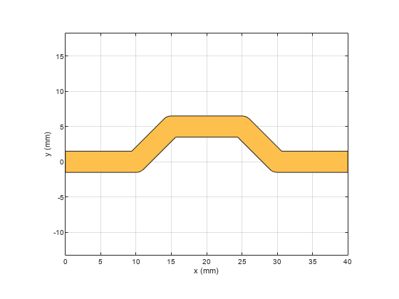
The output shows that the trace is created using the angle specified for each corresponding length input. The corners are specified as smooth and hence it creates curved edges.
Extend the Line Trace
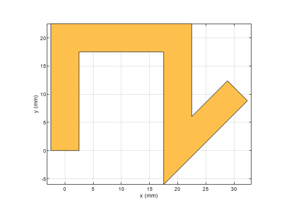
Add a 15 mm line perpendicular to the earlier trace. So add 15 mm to the Length property and 90 deg to the Angle property of the trace and set the corner to Miter.
trace.Length = [10 5*sqrt(2) 10 5*sqrt(2) 10 15]*1e-3;
trace.Angle  = [0 45 0 -45 0 90];
trace.Width  = 3e-3;
trace.Corner = "Miter";
figure;
show(trace);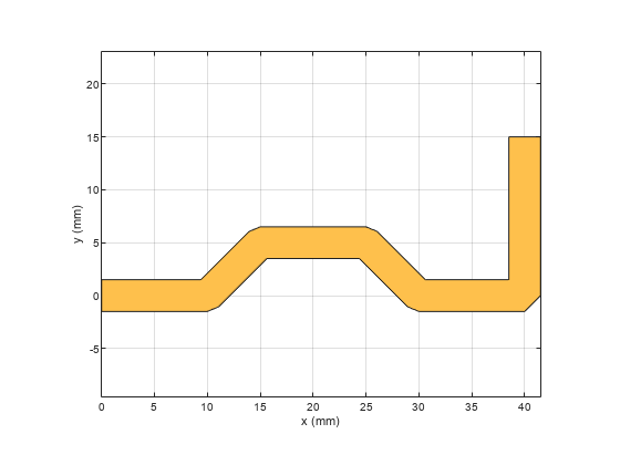
The output shows that the trace is created using the angle specified for each corresponding length input. The corners is specified as Miter and hence it creates mitered edges. Observe that the ends of the trace are at [0,0] and [40,15] mm where the feed points are assigned in the next section.
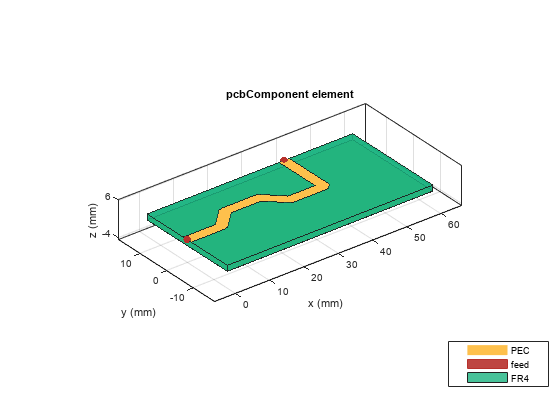
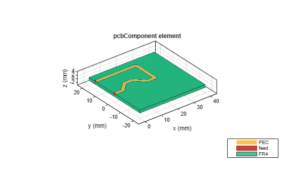
Create PCB Component
Use the pcbComponent to create the PCB stack for the shape. For creating a PCB stack, use the trace created as the top layer. The middle layer is a dielectric and the bottom layer is ground plane. Use the dielectric object to create the FR4 dielectric. Use traceRectangular object to create a rectangular ground plane. Assign the trace, dielectric(d), and groundplane to the Layers property on the pcbComponent. Assign the FeedLocations at the ends of the trace and visualize it.
pcb = pcbComponent;
d = dielectric('FR4');
d.Thickness = pcb.BoardThickness;
groundplane = traceRectangular('Length', 60e-3,'Width',30e-3,'Center',[60e-3/2,0]);
pcb.Layers = {trace,d,groundplane};
pcb.BoardShape = groundplane;
pcb.FeedDiameter = trace.Width/2;
pcb.FeedLocations = [0,0,1,3;40e-3,15e-3,1,3];
figure;
show(pcb);
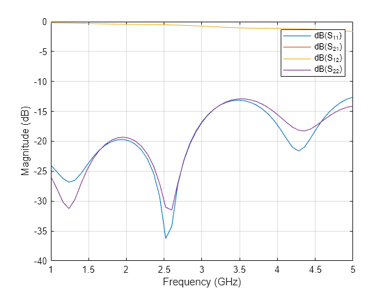
Use sparameters to calculate the s-parameters of the trace and plot it using rfplot function.
spar = sparameters(pcb,linspace(1e9,5e9,51));
figure;
rfplot(spar);
Point Trace
Use the tracePoint object to create a Point trace. Observe that the tracePoint has TracePoints, Width, and Corner as properties. Based on the Points, the tracePoint creates the trace and the Corner property is used to specify the type of corner at each bend i.e. you can specify either sharp, miter or smooth. Change the TracePoints and set the corner poperty to Miter
trace = tracePoint;
trace.TracePoints = [0 0;5 0;10 5;15 5;20 0;25 0]*1e-3;
trace.Corner = "Miter";
figure;
show(trace);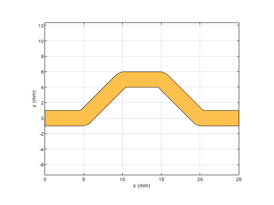
Extend the trace
Add an addional L-Shaped trace to the earlier trace so that the feed points are aligned to the same edge. Add two points in the TracePoints property as shown below. Set the Corner to Miter.
trace.TracePoints = [0 0;5 0;10 5;15 5;20 0;25 0;25 15;0 15]*1e-3;
trace.Corner = "Miter";
figure;
show(trace);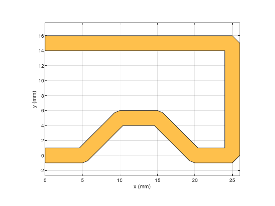
Create PCB Component
Use the pcbComponent to create the PCB stack for the shape. For creating a PCB stack, use the trace created as a top layer. The middle layer is a dielectric and the bottom layer is ground plane. Use the dielectric object to create the FR4 dielectric. Use traceRectangular object to create a rectangular ground plane. Assign the trace, dielectric(d) and groundplane to the Layers property on the pcbComponent. Assign the FeedLocations at the ends of the trace and visualize it.
pcb = pcbComponent;
d = dielectric('FR4');
d.Thickness = pcb.BoardThickness;
groundplane = traceRectangular('Length', 40e-3,'Width',40e-3,'Center',[40e-3/2,0]);
pcb.Layers = {trace,d,groundplane};
pcb.FeedLocations = [0,0,1,3;0e-3,15e-3,1,3];
pcb.BoardShape = groundplane;
pcb.FeedDiameter = trace.Width/2;
figure;
show(pcb);
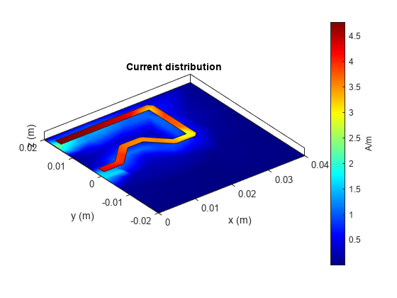
Use current function to plot the current distribution on the trace
figure;
current(pcb,1e9);
Use charge function to plot the charge on the trace
figure;
charge(pcb,1e9);
