Dual-Fed Square Microstrip Patch Antenna for BLE Applications
This example shows how to use the pcbComponent and pcbcascade functionality of RF PCB Toolbox™ to design and analyze the dual-fed square microstrip patch antenna for Bluetooth Low Energy (BLE) applications.
You can use different feed arrangements to achieve circular and elliptical polarization or by using two orthogonal modes excited with a 90 degree phase difference between them. The two orthogonal modes can be accomplished by adjusting the physical dimensions of the patch and using either single or multiple feeds. For a square patch element, the easiest way to excite for circular polarization is to feed the element at two adjacent edges, to excite the two orthogonal modes as shown in the figure. For a quadrature phase difference, feed the element with a 90 degree power divider or a 90 degree hybrid as shown in the figure below.

Create Variables
Centerfreq = 2.4e9;
freq       = linspace(2e9,3e9,41);
Design of Branchline Coupler
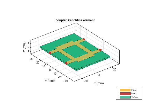
Use the design function on the couplerBranchline object to create a branchline coupler at the desired frequency and visualize it. The default substrate for branchline coupler is Teflon.
coupler = design(couplerBranchline,Centerfreq);
figure;
show(coupler);
Create Variables for Square Patch and Connecting Feed Lines
The patchLength variable creates a square patch. The feedLineWidth and feedLineLength variable creates the feed lines to the antenna. The portSpacing matches the gap between the feed lines to that of the output ports of the branchline coupler. The patchLength and feedLineLength are close to half wavelength at design frequency.
patchLength    = 41.9e-3;
feedLineLength = 65.7e-3;
feedLineWidth  = 3e-3;
portSpacing    = coupler.ShuntArmLength/2+coupler.PortLineWidth/2;
Use the traceRectangular object to create a square patch with side length as patchLength. Use the rotateZ function to rotate the shape by 45 degrees and visualize it.
patch    = traceRectangular('Length',patchLength,'Width',patchLength);
patch    = rotateZ(patch,45);
figure;
show(patch);

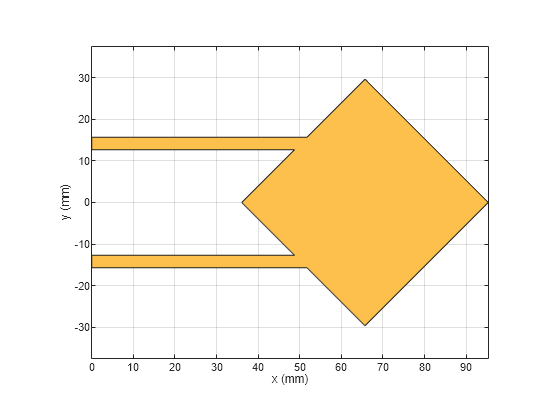
Use the traceRectangular object to create two feed lines with same length, width, and equal spacing on either side of the X-axis. Perform a Boolean add operation for the shapes patch, feedline1 and feedline2 and visualize it.
feedLine1 = traceRectangular('Length',feedLineLength,'Width',feedLineWidth,'Center',[-feedLineLength/2,portSpacing]);
feedLine2 = traceRectangular('Length',feedLineLength,'Width',feedLineWidth,'Center',[-feedLineLength/2,-portSpacing]);
antShape = patch+ feedLine1+ feedLine2;
figure;
show(antShape);

Translate the shape along the X-axis such that the feedlines are aligning at x = 0.
translate(antShape,[feedLineLength,0,0]);
Define the substrate parameters and create a dielectric object. Create a groundplane using the antenna.Rectangle object and use pcbStack to create a PCB antenna. Assign the dielectric and ground plane to the Layers property on pcbStack. Assign the FeedLocations to the edge of the feedline and set the BoardThickness to Height on the pcbStack and visualize the antenna.
EpsilonR     = coupler.Substrate.EpsilonR;    % Dielectric EpsilonR
Height       = coupler.Height;                % Height of the Substrate
LossTangent  = coupler.Substrate.LossTangent; % Loss Tangent of the Substate

d1  = dielectric('Name',{'Teflon'},'EpsilonR',EpsilonR,'LossTangent',LossTangent,'Thickness',Height);
Gnd = antenna.Rectangle('Length',120e-3,'Width',80e-3,'Center',[120e-3/2,0]);


ant = pcbStack;
ant.BoardThickness = Height;
ant.Layers = {antShape,d1,Gnd};
ant.BoardShape    = Gnd;
ant.FeedLocations = [0 portSpacing 1 3;0,-portSpacing 1 3];
figure;
show(ant);

Use the impedance function to plot the impedance of the antenna from 2.2 GHz to 2.6 GHz
figure;
impedance(ant,linspace(2.2e9,2.6e9,31));

The result shows that the impedance of the patch is around 400 ohms at 2.4 GHz. In order to match the impedance of the patch with the 50 ohm line, connect a quarter wavelength transformer at the end of the feedline to transform the impedance to 50 ohm. The impedance of the quarterwave transformer is the geometric mean of the impedances to be matched. Hence the geometric mean of 50 ohm and 400 ohm value comes out to be 141 ohms.
Use the microstripLine design to calculate the width of the line with a Z0 of 141 ohm.
line = microstripLine;
line.Height = coupler.Height;
line = design(line,Centerfreq,"LineLength",0.25,"Z0",141);
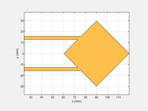
Use the traceRectangular object to create two quarter wave transformer lines with same length, width, and equal spacing on either side of the X-axis. Perform a Boolean add operation for the shapes patch, Line1 and Line2 and visualize it.
Line1     = traceRectangular('Length',line.Length,'Width',line.Width,'Center',[line.Length/2,portSpacing]);
Line2     = traceRectangular('Length',line.Length,'Width',line.Width,'Center',[line.Length/2,-portSpacing]);
translate(antShape,[line.Length,0,0]);
antShape  = antShape + Line1+ Line2;
show(antShape);

Define the substrate parameters and create a dielectric to use in the PCB stack of the antenna. Create a groundplane using the antenna.Rectangle shape.
Use the pcbStack to create a PCB antenna and assign the dielectric and ground plane to the Layers property on pcbStack. Assign the FeedLocations to the edge of the feedline and set the BoardThickness to Height on the pcbStack and visualize the antenna. The below code performs these operations and creates the PCB antenna.
EpsilonR     = coupler.Substrate.EpsilonR;    % Dielectric EpsilonR
Height       = coupler.Height;                % Height of the Substrat
LossTangent  = coupler.Substrate.LossTangent; % Loss Tangent of the Substate

d1  = dielectric('Name',{'Teflon'},'EpsilonR',EpsilonR,'LossTangent',LossTangent,'Thickness',Height);
Gnd = antenna.Rectangle('Length',120e-3,'Width',80e-3,'Center',[120e-3/2,0]);
ant               = pcbStack;
ant.BoardThickness = Height;
ant.Layers        = {antShape,d1,Gnd};
ant.BoardShape    = Gnd;
ant.FeedLocations = [0 portSpacing 1 3;0,-portSpacing 1 3];
figure,show(ant);

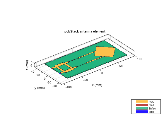
Use the pcbcascade object to join the coupler and the patch antenna. To obtain the circular polarization, connect the isolated port on the branchline coupler to a matched load of 50 ohm. The isolated port feed location in FeedLocations property of the pcbStack is copied into the ViaLocations. The feed location on the isolated port is deleted. The lumpedElement object is used to create an impedance of 50 ohms and the location of the Lumped Element is given at the ViaLocations. Assign this lumpedElement to the Load property on the pcbStack and visualize the antenna. The below code performs these operations.
pcbAntenna                    = pcbcascade(coupler,ant);
pcbAntenna.ViaLocations       = pcbAntenna.FeedLocations(2,:);
pcbAntenna.ViaDiameter        = pcbAntenna.FeedDiameter;
pcbAntenna.FeedLocations(2,:) = [];
r = lumpedElement;
r.Impedance = 50;
r.Location  = [pcbAntenna.ViaLocations(1:2),pcbAntenna.BoardThickness];
pcbAntenna.Load = r;
figure;
show(pcbAntenna);
Use the sparameters function to calculate the s-parameters of the antenna and plot the result using the rfplot function.
spar = sparameters(pcbAntenna,freq);
figure;
rfplot(spar);
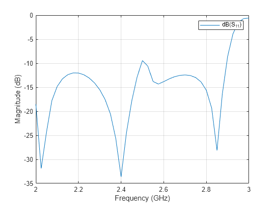
The result shows that the antenna is a good match from 2 GHz to 3 GHz.
Use the pattern function to plot the 3D radiation pattern of the antenna.
figure;
pattern(pcbAntenna,Centerfreq);
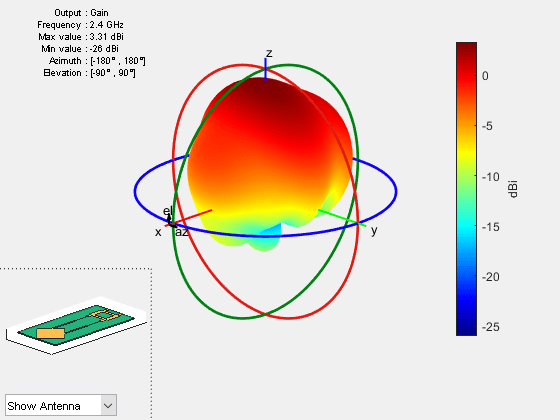
The antenna has a gain of around 7 dBi at the design frequency.
Use the axialRatio function to plot the axial ratio of the antenna at 2.45 GHz. Use the axial ratio to determine the polarization of the antenna. For the circular polarization, the axial ratio must be less than 3 dB.
figure;
axialRatio(pcbAntenna,Centerfreq,90,0:5:180);
title('Axial Ratio for Azimuth = 90 Plane');
The result shows that the axial ratio is below 3 dB for all the elevation angles and hence the antenna exhibits a circular polarization. In the orthogonal plane when azimuth angle is 0 degrees, the circular polarization is obtained between the elevation angles of 60 to 90 degrees.
Use the axialRatio function to plot the axial ratio of the antenna with frequency.
figure;
axialRatio(pcbAntenna,freq,0,90);
title('Axial Ratio with Frequency');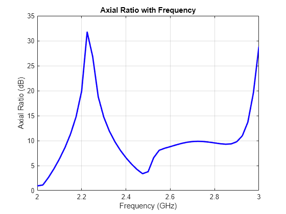
The axial ratio with frequency shows that the antenna exhibits circular polarization around 2.4 GHz.
References
[1] Balanis, C.A. "Antenna Theory. Analysis and Design", p. 860, Wiley, New York, 3rd Edition, 2005.