Model and Analyze Microstrip Interdigital Capacitor as Bandpass filter
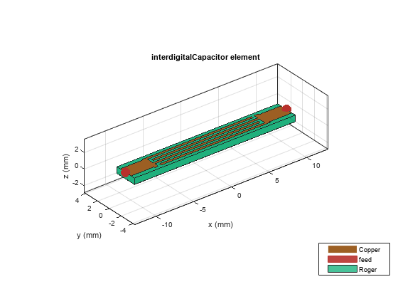
The interdigital capacitor (IDC) is a multi-finger periodic structure and is frequently used in the microstrip microwave integrated circuits for RF or microwave development. The interdigital capacitors use the capacitance that occurs across a narrow gap between conducting fingers. They are optimized based on applications.
This example shows the analysis of interdigital capacitor that shows band pass response in the frequency range of 3.5 GHz to 3.9 GHz. The capacitance is calculated in the desired range with and without de-embedding the effect of microstrip feeder line.
Create an interdigital capacitor and visualize it.
obj = interdigitalCapacitor;
figure;
show(obj);
Use the sparameters function to compute the s-parameters and plot it using the rfplot function from RF Toolbox to understand the behavior of the designed capacitor.
freq = linspace(2e9,8e9,51);
spar = sparameters(obj,freq);
figure;
rfplot(spar);
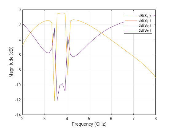
The s-parameters plot shows that the insertion loss is minimal in the frequency range of 3.5 GHz to 3.9 GHz which exhibits band pass like behavior. The capacitor exhibits low attenuation in this frequency range.
These kinds of capacitor are used in RF couple or DC blocks where the capacitor should have minimal attenuation and reflection when the signal goes through them.
Analyze the measure of capacitor without de-embedding the feeder line effect using the capacitance function from 3.5 GHz to 3.9 GHz. Use the mesh function to manually mesh the structure.
figure;
mesh(obj,'MaxEdgeLength',0.0017)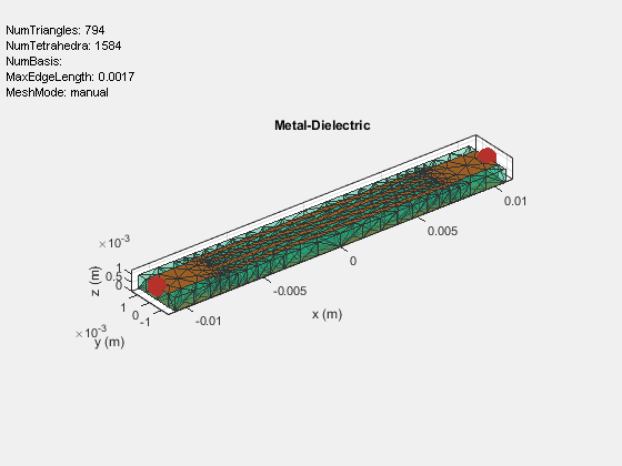
freq = linspace(3.5e9,3.9e9,21);
figure;
capacitance(obj,freq,'DeEmbed',0)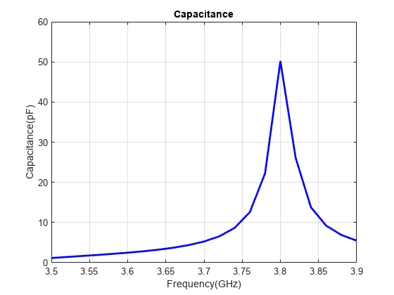
It is observed that there is a sudden spurious spike at 3.82 GHz which is due to the effect of the feeder line. Further to eliminate that effect the DeEmbed option in the capacitance method has to be enabled.
figure;
capacitance(obj,freq,'DeEmbed',1)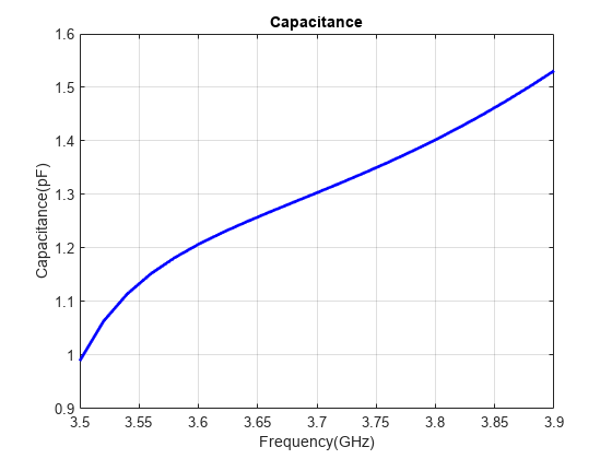
Hence, by de-embeddeding the effect of feeder line it subtracts the additional phase that is added due to the feed line. The capacitance of the capacitor is around 1 pF to 1.5 pF in the frequency range of 3.5 to 3.9 GHz.
The capacitance of the capacitor can be analyzed over the desired frequency range using different options such as de-embed the effect of the feeder line and include the parasitic effect by enabling the options in capacitance method.
Reference
[1] Dib, Nihad, Qiu Zhangb, and Ulrich Rohde. “New Cad Model of the Microstrip Interdigital Capacitor.” Active and Passive Electronic Components 27, no. 4 (2004): 237–45. https://doi.org/10.1080/08827510310001648870.