Model Uncertainty in Simulink for Robust Tuning
This example shows how to set up a Simulink® model for robust tuning against parameter uncertainty. Robust controller tuning or robust controller synthesis for a system modeled in Simulink requires linearizing the model such that the software takes parameter uncertainty into account. Doing so requires block substitution (Simulink Control Design) for linearization, to replace the value of blocks that have parameter uncertainty with uncertain parameters or systems.
In this example, you set up a model of a mass-spring-damper system for robust
tuning, where the physical parameters of the system are uncertain. The example shows
how to set up the model for robust tuning using software such as Control System
Tuner or systune for slTuner. It also
shows how to extract an uncertain system to use for robust controller design with
musyn.
Mass-Spring-Damper System
Open the Simulink model rct_mass_spring_damper.
openExample('rct_mass_spring_damper')
This model represents a system for controlling the mass-spring damper system of the following illustration.

In this system, the applied force F is the plant input. The
PID controller generates the force necessary to control the mass position
x. When the mass m, the damping
constant c, and the spring constant k are
fixed and known, tuning the PID coefficients for desired performance is
straightforward. In practice, however, physical system parameters can be
uncertain. You can use Control System Tuner or systune to
tune the system robustly against the uncertainty, and achieve satisfactory
performance within the range of expected values for these parameters.
Specify Parameter Uncertainty
The model is configured to use the nominal or most probable values of the physical parameters, m = 3, c = 1, and k = 2. To tune the system against uncertainty in these parameters, specify the parameter uncertainty in the model.
First, create uncertain real (ureal) parameters for each
of the three uncertainties. For this example, specify the uncertainty as a
percentage variation from the nominal value.
m_un = ureal('m',3,'Percentage',40);
c_un = ureal('c',1,'Percentage',20);
k_un = ureal('k',2,'Percentage',30);
To specify these uncertainties in the model, use block substitution. Block
substitution lets you specify the linearization of a particular block in a
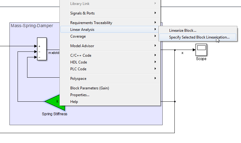
Simulink model. In the model, right-click the Spring
Stiffness block in the model and select Linear Analysis > Specify Selected Block Linearization.

In the Block Linearization Specification dialog box, check Specify
block linearization using one of the following and enter
k_un in the text field. Click
OK.

When you use Control System Tuner for this model, the software linearizes the
model and tunes the tunable parameters using that linearization to compute
system responses. Specifying k_un as the linearization of the
Spring
                        Stiffness
block causes the software to use the
uncertain parameter as the linearized value of the block instead of its nominal
value, which is a constant, fixed gain of 2.
Because the uncertain parameters in this model, such as the spring stiffness,
are implemented as scalar gain blocks, use a simple ureal
parameter as the block substitution. For more complex blocks, construct a
uss model that represents the uncertain value of the
entire block.
Note
Use block substitution to specify the uncertainty of the block even if the
block is an Uncertain LTI System block. Unless you
explicitly specify the uncertain value as the block substitution, Control
System Tuner and slTuner use the nominal value when
linearizing Uncertain LTI System blocks.
In the same way, specify c_un as the block linearization
for the Damping block. For the Mass block,
in the Block Linearization Specification dialog box, enter
1/m_un as the uncertain value, because the gain of this
block is the inverse of the mass.

Tune with Control System Tuner
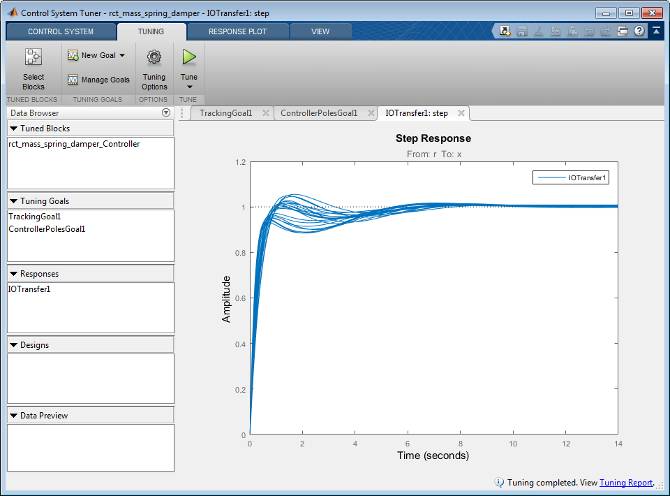
You can now open Control System Tuner for the model, create tuning goals, and tune the model. When you do so, Control System Tuner tunes the controller parameters to optimize performance over the entire range of uncertainty. Tuning-goal plots and response plots in Control System Tuner display multiple responses computed at random values of the uncertain parameters, as shown.

This sampling provides a general sense of the range of possible responses, but does not necessarily reflect the true worst-case response.
Configuration for slTuner
When you use slTuner for command-line tuning, you can
specify uncertainties in the model using the Block Linearization Specification
dialog box. Alternatively, you can specify the uncertain block substitutions
without altering the model. To do so, use a block-substitution structure when
you create the slTuner interface. For example, create a
block-substitution structure for the rct_mass_spring_damper
model.
blocksubs(1).Name = 'rct_mass_spring_damper/Mass';
blocksubs(1).Value = 1/m_un;
blocksubs(2).Name = 'rct_mass_spring_damper/Damping';
blocksubs(2).Value = c_un;
blocksubs(3).Name = 'rct_mass_spring_damper/Spring Stiffness';
blocksubs(3).Value = k_un;
Use this structure to obtain an slTuner interface to the
model with the uncertain values.
UST0 = slTuner('rct_mass_spring_damper','Controller',blocksubs);
You can now create tuning goals and tune the model.
systune tunes the system to optimize performance over
the entire range of uncertainty. For an example illustrating this robust-tuning
workflow with slTuner, see Robust Tuning of Mass-Spring-Damper System.
Extract uss Plant Model for Robust Controller Design with musyn
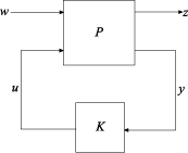
The musyn command synthesizes a robust controller for a plant
assuming an LFT control configuration.

Mapping this structure to the Simulink model,
w is the reference input
r, the output of the Step block.u is the control signal
F, the output of the PID Controller block.z is the plant output
x, the output of the Integrator block.y is the measurement signal, which is the controller input, or the output of the Sum block.
Use these signals with the getIOTransfer (Simulink Control Design) command to
extract the plant P from the slTuner
interface UST0. To do so, UST0 must have
analysis points defined at each of these locations. Examine the analysis points
of UST0.
getPoints(UST0)
ans =

  2×1 cell array

    {'rct_mass_spring_damper/Step/1[r]'      }
    {'rct_mass_spring_damper/Integrator/1[x]'}
There are already analysis points for w and z. Add the analysis points for u and y.
addPoint(UST0,{'Sum1','Controller'});
getPoints(UST0)
ans =
4×1 cell array
{'rct_mass_spring_damper/Step/1[r]' }
{'rct_mass_spring_damper/Integrator/1[x]'}
{'rct_mass_spring_damper/Sum1/1' }
{'rct_mass_spring_damper/Controller/1[F]'}
You can now extract the plant model P for tuning with
musyn. Use the analysis-point signal names, shown in
brackets in the output of getPoints, to specify the inputs
and outputs of P. For analysis points that do not have signal
names, use the block name.
Pg = getIOTransfer(UST0,{'r','F'},{'x','Sum'});getIOTransfer returns a genss model. In
this case, because Pg excludes the controller block,
Pg is a genss model with uncertain
blocks only. Convert Pg to uss for
controller design with musyn.
P = uss(P)
P =

  Uncertain continuous-time state-space model with 2 outputs, 2 inputs, 3 states.
  The model uncertainty consists of the following blocks:
    c: Uncertain real, nominal = 1, variability = [-20,20]%, 1 occurrences
    k: Uncertain real, nominal = 2, variability = [-30,30]%, 1 occurrences
    m: Uncertain real, nominal = 3, variability = [-40,40]%, 1 occurrences

Type "P.NominalValue" to see the nominal value, "get(P)" to see all properties, and
"P.Uncertainty" to interact with the uncertain elements.
You can now use musyn to design a robust controller for
P. For instance, to design an unstructured robust
controller, note that P has one measurement signal and one
control signal, and use the following command.
[K,CLperf,info] = musyn(P,1,1);
Alternatively, design a fixed-structure PID controller, as in the original Simulink model.
C0 = tunablePID('K','PID');
CL0 = lft(P,C0);
[CL,CLperf,info] = musyn(CL0);
For more information about robust controller design, see musyn.
See Also
slTuner (Simulink Control Design) | systune | systune (for slTuner) (Simulink Control Design) | musyn | getIOTransfer (Simulink Control Design)