Turn Robot Using LCD Button Press and Display Gyroscope Reading on LCD Screen
This example shows you how to use Simulink® Coder™ Support Package for ARM® Cortex®-based VEX® Microcontroller to create an application in which a 4-wheeled robot turns by a degree of angle chosen by the user from the options displayed on an LCD screen. The VEX LCD screen displays 3 angle values. The user can select an angle or a combination of two or more angles by pressing the corresponding LCD buttons. Accordingly, the robot rotates by the specified degree of angle in anti-clockwise direction.
Introduction
Simulink Coder Support Package for ARM Cortex-based VEX Microcontroller enables you to create and run Simulink models on a VEX microcontroller.
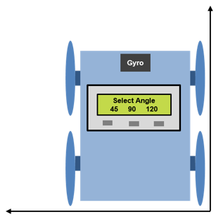
In this example, you will learn how to use VEX Gyroscope and VEX LCD Display to create an application where the robot turns by an angle selected by the user. In this application, the LCD screen displays three angles 45, 90 and 120 corresponding to the left, center and right LCD buttons. The user can select either of the three angles by pressing the corresponding LCD button or can select a combination of two or more angles by pressing the corresponding buttons together. The 4-wheeled robot then takes a turn in the anti-clockwise direction until the turn angle specified by the user is completed. To make the robot turn, the left and right motors are provided with speed input such that the motors rotate in opposite direction. The figure below illustrates this application.

Prerequisites
If you are new to Simulink, we recommend watching the Simulink Quick Start video.
We recommend completing Getting Started with VEX Microcontroller Support Package.
Required Hardware
To run this example you will need the following hardware:
ARM Cortex-based VEX Microcontroller
VEX Yaw Rate Gyroscope Sensor
VEX LCD Display
Standard DC Motors (2) and Motor Controller 29 (2)
4-wheel robot platform
3-wire cable
VEXnet Gamepad and VEXnet keys
7.2V Battery
USB type A-Male to A-Male cable
Below is a figure of a 4-wheel robot platform with gyroscope sensor and LCD display and two DC motors connected to the two wheels and attached to the VEX microcontroller.

Task 1 - Hardware Connections
1. The two DC motors drive the left and right set of wheels on the robot platform. The motors are installed on the robot with the motor shafts facing outwards to enable connecting the wheels to the shafts. Connect the left DC motor and right DC motor to motor pins 4 and 3 respectively on the VEX microcontroller. Use the Motor Controller 29 cables to establish the connection between the motor leads and the pins on the VEX microcontroller. Connect them as described on Page 4 of the VEX Microcontroller and VEXnet Joystick User Guide.
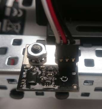
2. Mount the VEX Gyroscope sensor on the front towards the center of the 4-wheel robot platform. Connect a 3-wire cable to the gyroscope such that the black wire of the cable is plugged into the pin near the 'B' printed on the sensor as shown in the figure below. Plug the other end of the 3-wire cable into analog port 1 of the VEX microcontroller.
3. Mount the VEX LCD Display on the 4-wheel robot platform. Plug the 3-pin ends of the serial Y-cable to the LCD Display, with the yellow wire connected to the RX port and the white wire connected to the TX port of the LCD Module. Plug the 4-pin end of the serial Y-cable into UART1 port on the VEX microcontroller.
4. Connect the battery supply to the VEX microcontroller.
Task 2 - Build and Download a Simulink Model to Calibrate the Gyroscope Sensor
In this task, you will learn how to use the Gyroscope block in a Simulink model and calibrate the gyroscope sensor to make its reading as accurate as possible.
The VEX gyroscope sensor output is affected by external factors such as temperature, mechanical vibration and motor magnetic field influence. This variation in gyroscope output is referred to as drift. The drift in gyroscope value can be corrected and the sensor can be calibrated to provide accurate readings using the Calibration multiplier parameter for the Gyroscope block. A default value of '196' for Calibration multiplier is used for the purpose of calibrating the gyroscope. This value may need to be increased or decreased for the gyroscope used so that the readings are accurate. In this task, you will learn how to calibrate the gyroscope sensor so that its angle output matches with the physical turn angle of the robot. The 4-wheeled robot is made to turn by an angle of 90 degrees in anti-clockwise direction with the help of the gyroscope reading. Based on how the robot rotates, i.e. beyond 90 degrees or less than 90 degrees, the Calibration multiplier parameter is increased or decreased until the gyroscope output angle matches with the physical turn angle made by the robot.
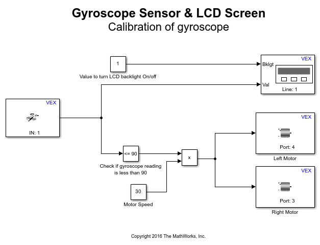
1. Open the pre-configured vexarmcortex_gyrocalibrate model.
2. Note the following points in the Simulink model.
The value for the parameter Analog port for the Gyroscope block is chosen as per the hardware connection in Task 1. The parameter Calibration multiplier for the Gyroscope block has a default value of '196'. The parameter Motor Channel for the Left Motor block is chosen as '4' and for the Right Motor block as '3' as per the hardware connections in Task 1. Similarly, the value for the parameter UART port for the LCD screen is chosen as 'UART1'.
In this model, the output of Gyroscope block is provided as input to the LCD Screen block. This will cause the Gyroscope block output to be displayed on the LCD Display. The output of Gyroscope block increases for anti-clockwise rotation and decreases for clockwise rotation.
The output of Gyroscope block is also connected to the input of Compare to Constant block whose Constant Value parameter value is '90'. This performs a comparison to check if the gyroscope reading is less than or equal to 90. The output of Compare to Constant block will be 1 as long as the gyroscope reading is less than or equal to 90.
The product of Compare to Constant and Constant block outputs is provided as speed input to the DC motors. As the left and right motors are attached to the robot platform with their shafts facing outwards, providing speed input of same sign to both motors makes them rotate in opposite directions, causing the robot to turn. Therefore, the robot will turn in the anti-clockwise direction till the gyroscope reading is less than or equal to 90. Note that the Gyroscope block output decreases for clockwise rotation. To rotate the robot in clockwise rotation, change the value of parameter Operator to '>=' and parameter Constant value to '-90' for Compare to Constant block and change the sign of speed input to DC motors.
3. In the Simulink model, go to the Modeling tab and click Model Settings.
4. When the Configuration Parameters page opens up, navigate to the Hardware Implementation pane.
Set the Hardware board to ARM Cortex-based VEX Microcontroller.
5. In the Configuration Parameters page, navigate to Solver pane and set the Solver to discrete (no continuous states).
6. Click OK.
7. Before building the model, make sure to connect the VEX Microcontroller to your computer with a USB A-Male to A-Male cable.
8. In the Simulink model, go to the Hardware tab and click Build, Deploy, and Start. The model will now be deployed to the VEX microcontroller.

9. Disconnect the USB cable from the VEX microcontroller and connect the VEXnet key to the VEX microcontroller. Place the robot on a sheet which has a right angle drawn on it similar to what is shown in the figure below.
10. Turn ON the VEX Microcontroller and the Gamepad to pair the VEXnet keys. Do not move the robot after turning ON the microcontroller for proper initialization of the gyroscope sensor. Once the VEXnet keys are paired, the robot begins to turn in the anti-clockwise direction. The LCD Display displays the output of Gyroscope block. When the robot stops turning, observe the value displayed on the LCD Display and measure the physical angle by which the robot has turned.
11. If the physical turn angle made by the robot is less than what is read by the gyroscope as observed from the LCD Display, decrease the value of the parameter Calibration multiplier for the Gyroscope block. If the physical turn angle made by the robot is more than what is read by the gyroscope, increase the value of the parameter Calibration multiplier.
12. Repeat steps 7 to 11 with different values for Calibration multiplier parameter until the gyroscope reading is as close as possible to the physical turn of the robot, which is 90 degrees in this case.
13. Note the value of the Calibration multiplier parameter after Step 12 is completed. This value will be used in Task 3 below.
Task 3 - Build and Download the Simulink Model to Turn Robot by Selected Angle
In this task, you will learn how to use the LCD Display to display the robot turn angles and choose the desired angle of turn by pressing the appropriate LCD button. You will also learn how to use gyroscope to turn the robot by the specified number of degrees.
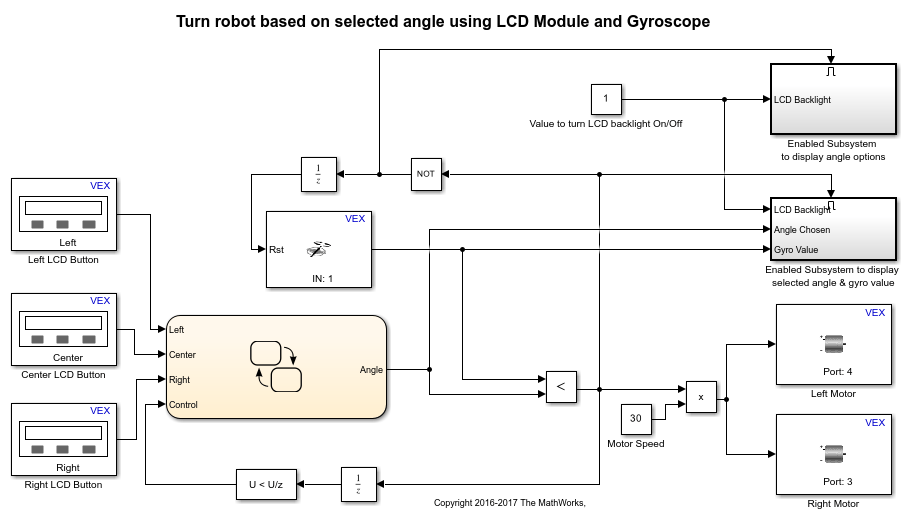
1. Open the pre-configured vexarmcortex_gyro_lcd model.
2. Double-click the Gyroscope block in the model to view its block parameters. Change the value of the parameter Calibration multiplier to that obtained in Task 2.
3. Note the following points in the Simulink model.
The value for the parameter Analog port for the Gyroscope block is chosen as per the hardware connection in Task 1. The three LCD Button blocks in the model have the values 'Left', 'Center' and 'Right' respectively for the parameter Button. The LCD Button blocks and the LCD Screen blocks in the Enabled Subsystems have the value of 'UART1' for the parameter UART port as per the hardware connections in Task 1. Similarly, the parameter Motor Channel for the Left Motor block is chosen as '4' and for the Right Motor block as '3'.
The outputs of the three LCD Button blocks corresponding to the three buttons are provided as inputs to the Stateflow Chart. The Stateflow® chart implements the logic to output the angle of turn based on the button(s) pressed using various states. The default output 'Angle' of the Stateflow chart is zero. It also includes the logic to reset the angle of turn to zero when the required degree of turn is completed. The implementation of the logic to output the angle of turn or reset the angle of turn is shown in the figure below.
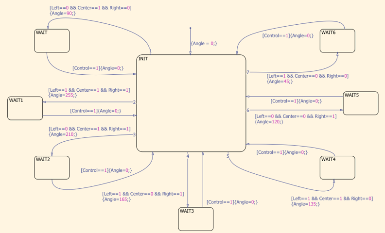
See Getting Started with Stateflow for an introduction to implementing states in Stateflow.
The Gyroscope block output is compared against the output 'Angle' of the Stateflow chart using the Relational Operator block with the '<' operator. By default, the comparison output is zero since the default gyroscope reading and the default stateflow chart output has a value of zero. The comparison output is 1 as long as the 'Angle' value is non-zero and the gyroscope reading is less than the 'Angle' value. The comparison output is used for the following purposes:
The comparison output is multiplied by a Constant block with value '30' to provide the speed input to the DC motors. Therefore, the DC motors are provided with a non-zero speed input as long as the gyroscope reading is less than the Stateflow chart output. As the left and right motors are attached to the robot platform facing outwards, providing speed input of same sign to both motors makes them rotate in opposite directions, causing the robot to turn.
The comparison output is also used to enable or disable the Enabled Subsystems named as Enabled Subsystem to display angle options and Enabled Subsystem to display selected angle & gyro value. Enabled Subsystem is a subsystem that executes at time steps for which the enable input has a positive value. Enabled Subsystem to display selected angle & gyro value is enabled when the comparison output is 1. The comparison output is inverted using the NOT logical operator and this inverted value enables the subsystem that displays the angle options when the comparison output is zero. Refer Create an Enabled Subsystem for more information on enabled subsystems.
The inverted comparison output is used as the external signal to reset the Gyroscope block output. This causes the gyroscope reading to be reset when no angle is selected via pressing the LCD buttons or the selected angle of turn is completed.
The comparison output changes from 1 to 0 when the selected angle of turn is completed. This change in the comparison value is detected using the Detect Decrease block, whose output is provided as the 'Control' input to the Stateflow chart. The 'Control' input is used to return to the initial default state in the Stateflow chart, thereby resetting the output 'Angle' to zero.
The reset signal to the Gyroscope block and the 'Control' input to the Stateflow chart are provided as inputs through Unit Delay blocks to avoid algebraic loops. An algebraic loop occurs when the block output depends on the input value and the input directly controls the output value. See Algebraic Loops for details on Algebraic loops.
4. Perform steps 3 to 8 from Task 2 above to build and download this Simulink model on the VEX Microcontroller.
5. Disconnect the USB cable from the VEX microcontroller and connect the VEXnet key to the VEX microcontroller. Place the robot on the ground. Turn ON the VEX microcontroller and the Gamepad to pair the VEXnet keys. Do not move the robot while the VEXnet keys are in the process of pairing. Once the VEXnet keys are paired, the LCD screen displays the turn angle options. Select the desired angle by pressing the corresponding LCD button(s). You will then observe that the robot begins to turn and stop once the specified angle of turn is completed.