MAT-file Logging on an SD Card on NXP FRDM-K64F Board
This example shows you how to perform MAT-file logging from a Simulink® model on a Micro SD card mounted on NXP FRDM-K64F board.
Introduction
Simulink Coder Support Package for NXP FRDM-K64F Board supports logging of signals from Simulink® model. These signals are logged as MAT-file(s) on a Micro SD card mounted on NXP FRDM-K64F board.
Signal logging enables you to monitor the signal behavior and to perform any historical analysis of the data. The data can be saved in any of these formats: Structure, Structure with time, or Array. You can save the signals using the following blocks:
To Workspace
Scope
Output port
This example provides you with the workflow to enable MAT-file logging and obtain the MAT-file on a Micro SD card mounted on NXP FRDM-K64F board.
Required Hardware
To run this example, you need the following hardware:
NXP FRDM-K64F board
USB type A to Micro-B cable
Micro SD card
Step 1 - Prepare the Connection and Configure a Simulink Model for MAT-File Logging
The MAT-file logging needs to be configured on the Simulink model so that the selected signals are logged on the Micro SD card on NXP FRDM-K64F board.
Tip: To learn how to setup a Simulink model for NXP FRDM-K64F, see Getting Started with Simulink Coder Support Package for NXP FRDM-K64F Board
1. Connect the NXP FRDM-K64F Board to your computer using a USB cable.
2. Insert the Micro SD card in the slot provided on the board.
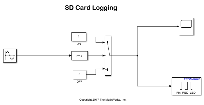
3. Open the SD Card Logging model. This Simulink model is pre-configured for the NXP FRDM-K64F target with MAT-File logging enabled. In this example, signals from the Scope block are logged.
open_system('freedomk64f_matfile_logging');

4. Open the Model Configuration Parameters dialog box for the Simulink model (click the gear icon on the Simulink® toolbar).

5. To enable MAT-file logging, go to Code Generation > Interface > Advanced Parameters. Alternatively, you can type MAT-file logging in the search box at the top of the dialog box. Select the MAT-file logging checkbox.
6. Click Apply and then OK.
7. Double-click the Scope block in the Simulink model. In the Scope dialog box, click the gear icon (Configuration Properties).
8. In the Configuration Properties: Scope dialog box, open the Logging tab, and select Log data to Workspace.
8. Click Apply and then OK.
9. On the Simulink toolbar, enter a value for the Simulation stop time. This is the duration for which the signal is logged. However, the model continues to run on the hardware and it is not affected by the time specified.
For example, in this demo model, the Simulation stop time is 10. The signal will be logged for 10 seconds. If the Simulation stop time is Inf, the signal will be logged till the Micro SD card is full or the board is disconnected.
Step 2 - Deploy the Model on NXP FRDM-K64F Board and View the MAT-files
After the Simulink model is configured for MAT-file logging, you can deploy the model on the connected NXP FRDM-K64F hardware and view the MAT-file(s) created on the Micro SD card.
Tip: To learn more about logging data, see Log Signals on SD Card
1. In the Simulink model, click the Deploy To Hardware button on the Simulink toolbar. The build process for the model starts and it is deployed on the NXP FRDM-K64F board. On successful deployment of the model, the LED on the board starts blinking.
2. To view the logged MAT-files, remove the Micro SD card from the board after the Simulation time, and insert the card on your computer.
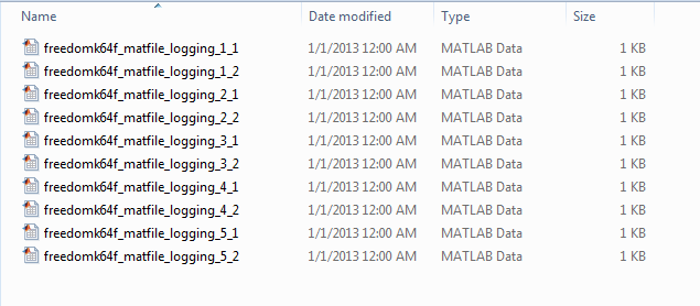
If the deployment of the model was successful, the MAT-files are generated on the Micro SD card as shown below:

After importing the MAT-files to your computer, you can use it for further analysis in MATLAB®.
Because the model running on the hardware creates multiple MAT-files, the logged data points are distributed across the generated MAT-files. You can create a stitcher function to combine these MAT-files into a single MAT-file that contains all the logged data points. To view an example of a MAT-file stitcher and understand its usage, enter the following command in the MATLAB® command window.
edit('Freedomk64f_MAT_stitcher.m');
Other things to try with MAT-file Logging on SD Card
In this example, a Scope block is used to log signals. However, the signals in a Simulink® model can also be logged on the SD card using the To Workspace block or by logging the output(s) of the Simulink® model. Explore the MAT-file logging of a Simulink model using these two techniques.
